
Flash lens of electronic device

a technology of electronic devices and flash, applied in the field of flash lenses, can solve the problems of flash not being able to cover the field of view of the camera, especially in the field of mobile device camera cameras

Pending Publication Date: 2022-07-07
SAMSUNG ELECTRONICS CO LTD
View PDF0 Cites 0 Cited by
  • Summary
  • Abstract
  • Description
  • Claims
  • Application Information

AI Technical Summary

Benefits of technology

This patent text describes a flash lens that reduces glare and improves the difference in brightness between the peripheral portion of an image. The flash lens prevents glare by evenly flashing the light emitted from the flash when capturing images in the dark. The flash lens has a unique design with different transparencies between areas, allowing for a uniformity of light that reaches the subject or background. This results in a flash lens that prevents glare and prevents the background from darkening by causing the emitted light to evenly reach the subject when taking a picture.

Problems solved by technology

According to the prior art, the emission angle of effective flash light of the electronic device is 76 degrees, and the flash may not be able to cover the field of view of the cameras.
Since the subject is located in the center of the light emitted from the flash, the subject may receive a relatively large amount of light, thereby causing glare.
This may be particularly problematic in cameras of mobile devices.

Method used


Image

  • Flash lens of electronic device
  • Flash lens of electronic device
  • Flash lens of electronic device

Examples


Embodiment Construction

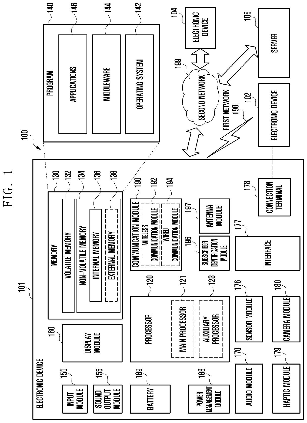
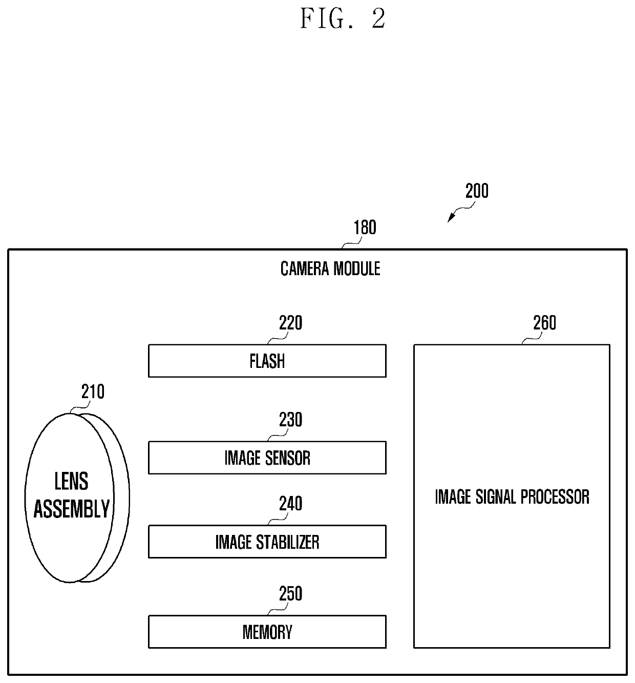
[0036]FIG. 1 is a block diagram illustrating an electronic device 101 in a network environment 100 according to various embodiments. Referring to FIG. 1, the electronic device 101 in the network environment 100 may communicate with an electronic device 102 via a first network 198 (e.g., a short-range wireless communication network), or an electronic device 104 or a server 108 via a second network 199 (e.g., a long-range wireless communication network). According to an embodiment, the electronic device 101 may communicate with the electronic device 104 via the server 108. According to an embodiment, the electronic device 101 may include a processor 120, memory 130, an input device 150, a sound output device 155, a display device 160, an audio module 170, a sensor FIG. 1 is a block diagram illustrating an electronic device 101 in a network environment 100 according to various embodiments. Referring to FIG. 1, the electronic device 101 in the network environment 100 may communicate wit...


PUM

PropertyMeasurementUnit
emission angleaaaaaaaaaa
wide angle of viewaaaaaaaaaa
field of viewaaaaaaaaaa

Abstract

An electronic device according to an embodiment may include a first camera module, and a flash module disposed adjacent to the first camera module, where the flash module may include an LED configured to emit light, and an optical lens disposed in the traveling direction of the light emitted from the LED. The optical lens may include a first surface in the direction facing the LED and a second surface in the direction opposite the first surface, and the second surface of the optical lens may include a first translucent area including a central area where the light emitted from the LED is incident and a second translucent area spaced apart from the first translucent area. Various other embodiments may be also provided.

Description

CROSS-REFERENCE TO RELATED APPLICATION(S)[0001]This application is a continuation of International Application No. PCT / KR2021 / 017060, filed on Nov. 19, 2021, which claims priority to Korean Patent Application No. 10-2021-0001895, filed on Jan. 7, 2021 in the Korean Intellectual Property Office, the disclosures of which are herein incorporated by reference.TECHNICAL FIELD[0002]One or more embodiments of the instant disclosure generally relates to an electronic device, for example, a flash lens of an electronic device.BACKGROUND ART[0003]As information and communication technologies have developed, semiconductor technology, and various electronic devices provide various functions have also developed. For example, the various functions may include functions related to voice calls, messages, broadcasts, the wireless Internet, cameras, and / or the reproduction of music.[0004]An electronic device having a camera embedded therein is a recent trend, and interest in various methods for taking...

Claims


Application Information

Patent Timeline
Patent Type & Authority Applications(United States)
IPC IPC(8): H04N5/225G02B19/00
CPCH04N5/2254G02B19/0061H04N5/2256H04N5/2258H04N23/45H04N23/56G03B15/05H04N23/00G03B2215/0567G03B2215/0592H04N23/55
Inventor KANG, TAEUKLEE, JIWOO
Owner SAMSUNG ELECTRONICS CO LTD
Learn More