
Eureka
For R&D, Eureka makes reading and utilizing patents & technical documents easy.
Eureka AIR
Designed for self-driven R&D workflows. Generate viable solutions, solve complex R&D challenges, empower your innovation with AI.

Eureka Materials
Designed for material experts only. Revolutionize your material R&D, from search, analyze, to developing new materials.

TechResearch
Generate reliable direction feasibility study reports for your R&D in just a few steps.

TechSeek
Discover and master advanced knowledge NOW. Basics, ideas, possibilities, all at once.

TechMind
As an expert in R&D Theories, TechMind can generates customized viable solutions instantly.

TechRisk
Analyze your overall solution with one click, know your potential R&D risks in advance.

TechMonitor
Get weekly tech updates, stay abreast of the latest tech innovations and key insights.
Estimation apparatus, transmission rate estimation method, and program
- Summary
- Abstract
- Description
- Claims
- Application Information
AI Technical Summary
Benefits of technology
Problems solved by technology
Method used
Image

Examples
first example embodiment
[0032]The first example embodiment will be described in further detail with reference to the drawings.
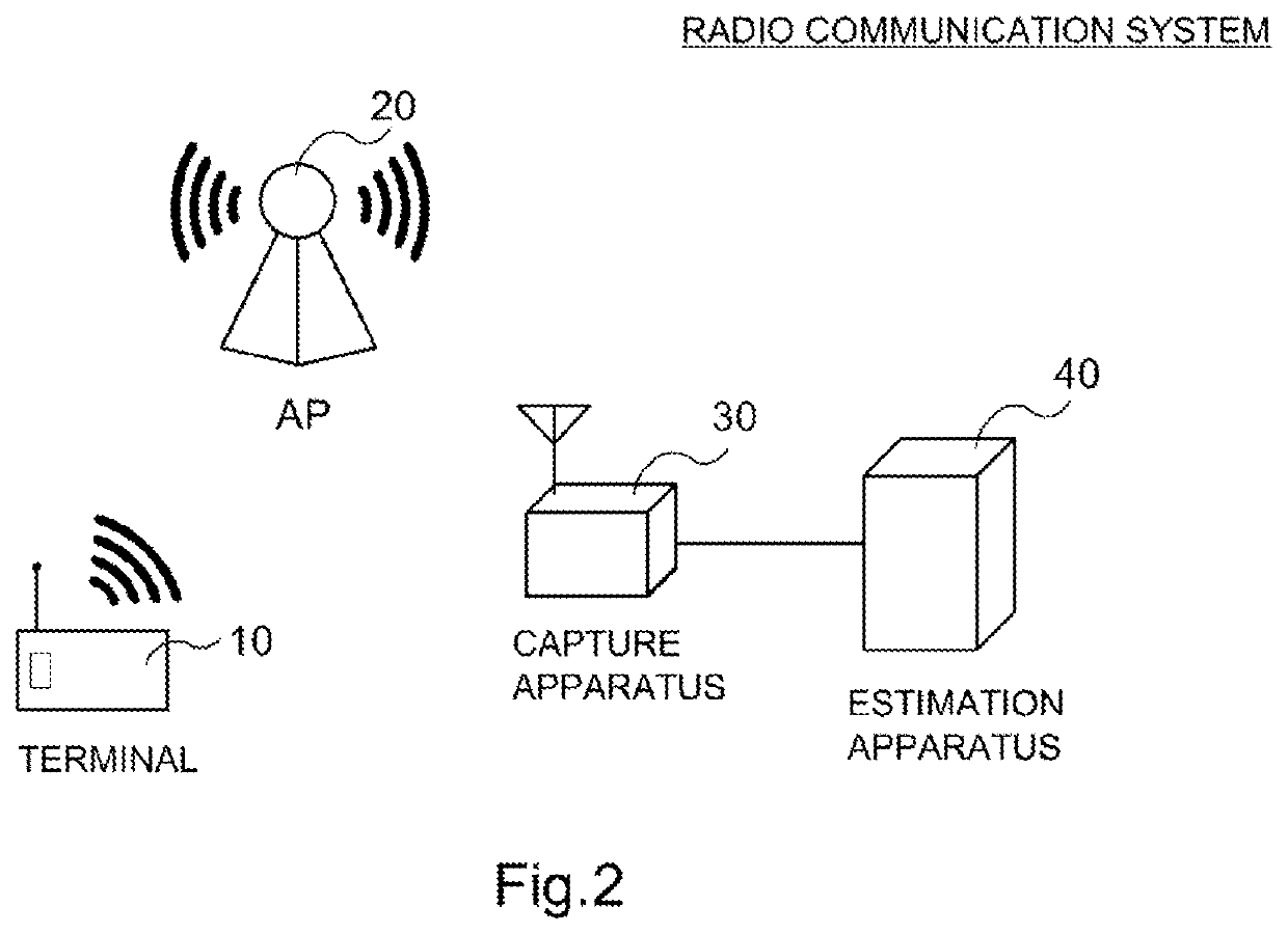
[0033]FIG. 2 is a diagram illustrating an example of a schematic configuration of a radio communication system according to the first example embodiment. With reference to FIG. 2, the radio communication system includes a terminal 10, an access point (AP) 20, a capture apparatus 30, and an estimation apparatus 40.
[0034]The configuration of the radio communication system illustrated in FIG. 2 is an example, and is not to limit the number of terminals 10 or the like. For example, it is only necessary that at least one or more terminals 10 be included in the radio communication system. In FIG. 2, the capture apparatus 30 and the estimation apparatus 40 are connected directly; however, these apparatuses may be connected via a network. Alternatively, the capture apparatus 30 may be installed in a field including the terminal 10 and the access point 20, and the estimation apparatus 40 may...
example alterations
[0110]The configuration, the operation, and the like of the radio communication system described in the example embodiment are merely examples, and are not to limit the configuration and the like of the system.
[0111]For example, the functions of the capture apparatus 30 and the estimation apparatus 40 may be implemented by one apparatus. More specifically, the function of the estimation apparatus 40 may be provided in the capture apparatus 30.
[0112]In the example embodiment, the transmission rate of the non-captured radio frame is estimated using three statistical values (the capture rate, the retransmission ratio, and the average value of the transmission rate). However, the estimation apparatus 40 can also estimate the transmission rate of the non-captured radio frame by using a part of the three statistical values. For example, the estimation apparatus 40 may estimate the transmission rate, with any one of the statistical values being set to a fixed value, and values calculated f...
PUM
 Abstract
Description
Claims
Application Information
 - R&D Engineer
- R&D Manager
- IP Professional
- Industry Leading Data Capabilities
- Powerful AI technology
- Patent DNA Extraction
Browse by: Latest US Patents, China's latest patents, Technical Efficacy Thesaurus, Application Domain, Technology Topic, Popular Technical Reports.
© 2024 PatSnap. All rights reserved.Legal|Privacy policy|Modern Slavery Act Transparency Statement|Sitemap|About US| Contact US: help@patsnap.com