
Device for degassing a liquid flowing in a liquid line

Pending Publication Date: 2022-08-18
NORMA GERMANY GMBH
View PDF0 Cites 0 Cited by
  • Summary
  • Abstract
  • Description
  • Claims
  • Application Information

AI Technical Summary

Benefits of technology

The patent describes a device that can quickly remove gas from a liquid flowing through a liquid line. This device can be easily connected to other liquid lines to remove gas from an entire system. It can also have a quick-action connector that allows for quick and easy connection to other lines. The technical effect of this device is to reduce the time required for degassing.

Problems solved by technology

However, this is a time-consuming and thus cost-intensive process.
This means that wetting of the material by the liquid is more difficult than wetting of a material which is not liquid-repellent.

Method used


Image

  • Device for degassing a liquid flowing in a liquid line
  • Device for degassing a liquid flowing in a liquid line

Examples


Embodiment Construction

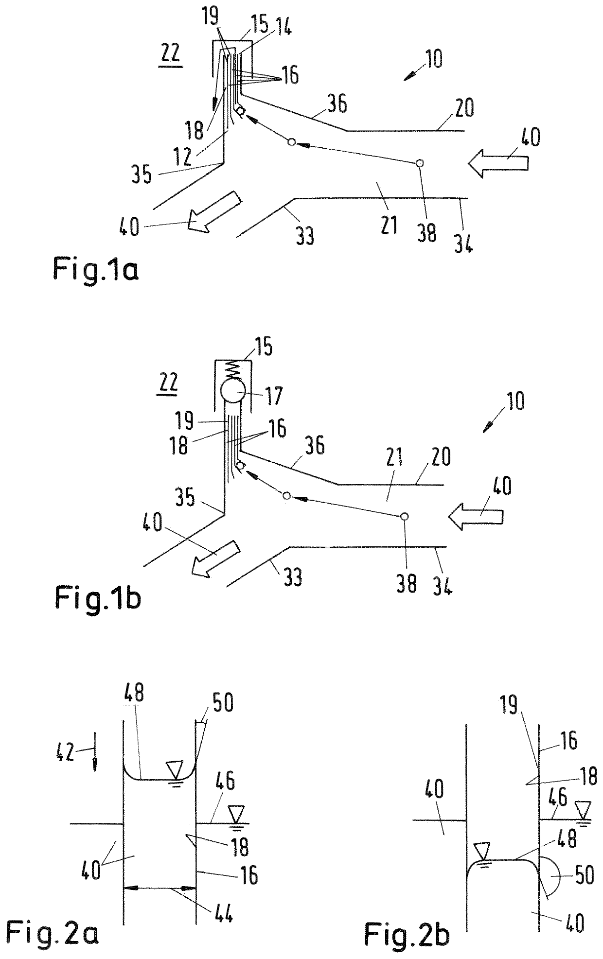
[0037]FIG. 1a illustrates a device 10, which is connected to a liquid line 20.

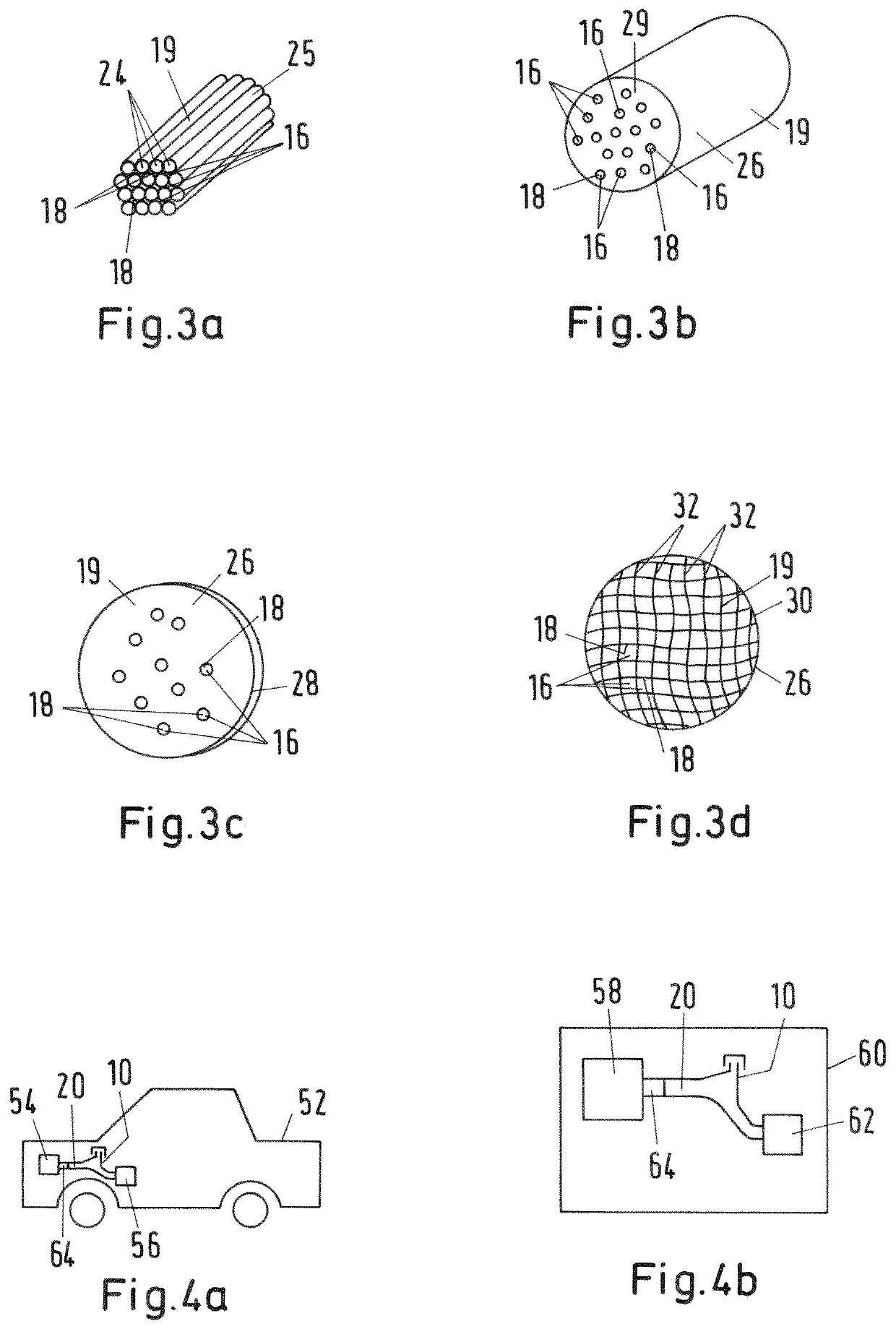
[0038]Here, the device 10 comprises an inlet opening 12, an outlet opening 14 and a capillary element 16. In this case, the device 10 has a multiplicity of capillary elements 16. The inlet opening 12 is connected in a fluid-communicating manner to a flow channel 21 of the liquid line 20. Furthermore, the capillary element 16 connects the outlet opening 14 to the inlet opening 12 in a fluid-communicating manner. The outlet opening 14 is connected to the environment 22 of the liquid line 20 in a fluid-communicating manner.

[0039]Hence, the flow channel 21 is connected to the environment 22 in a fluid-communicating manner via the device 10.

[0040]The capillary element 16 has an inner wall surface 18, which delimits a flow channel of the capillary element 16. Arranged on the inner wall surface 18 is a material 19 which is liquid-repellent with respect to the liquid 40 which flows through the liquid line 20. In t...


PUM

PropertyMeasurementUnit
Timeaaaaaaaaaa
Pressureaaaaaaaaaa
Radiusaaaaaaaaaa

Abstract

A device for degassing a liquid flowing in a liquid line is provided. The device has an inlet opening, an outlet opening, and a capillary element having an inner wall surface. The capillary element extends between the inlet opening and the outlet opening. The inlet opening is connected in a fluid-communicating manner to the outlet opening and is connected in a fluid-communicating manner to the liquid line. The inner wall surface has a material that is liquid-repellent for a liquid flowing in the liquid line. A device is thus provided for degassing a liquid flowing in a liquid line that reduces the time needed for degassing.

Description

INTRODUCTION[0001]The disclosure relates to a device for degassing a liquid flowing in a liquid line.[0002]In cooling systems or temperature management systems, in particular of electric vehicles, liquids are used to redistribute thermal energy. Here, the liquids are carried in liquid lines. To increase the efficiency of thermal energy transfer, it is necessary in this case to remove from the liquid lines gases which are located in the liquid lines or penetrate into the liquid lines because of leaks. The liquid lines are therefore regularly degassed.[0003]For this purpose, there is a known practice of providing valves on the liquid lines, with which a user can release the gas from the liquid line by opening the valve. In this case, the user opens the valve until the gas has flowed out and liquid emerges from the valve. This process is repeated by the user at regular intervals in order to regularly remove gases which have penetrated into the liquid line from the system. However, this...

Claims


Application Information

Patent Timeline
IPC IPC(8): B01D19/00
CPCB01D19/0042B01D19/0063B01D19/0031B01D19/0073F01P11/028F01P2011/0271F01P11/0238B60K2015/03509B01D46/003
Inventor KINTEA, DANIELVON BREITENBACH, GERRITKIRMANN, JEAN-LUCUNGER, DENNIS
Owner NORMA GERMANY GMBH
Learn More