Motor and rotor structure thereof

Pending Publication Date: 2022-08-25
NAT CHENG KUNG UNIV
View PDF15 Cites 0 Cited by
  • Summary
  • Abstract
  • Description
  • Claims
  • Application Information

AI Technical Summary

Benefits of technology

The present invention provides a rotor structure for a motor that has higher strength and less stress concentration while running. The amount of deformation and displacement of the rotor core and magnetic member unit is small. This results in improved motor performance and efficiency.

Problems solved by technology

Therefore, the structural strength of the above-mentioned motor structure is limited, and the rotational speed cannot be further increased.

Method used


Image

  • Motor and rotor structure thereof
  • Motor and rotor structure thereof
  • Motor and rotor structure thereof

Examples


Embodiment Construction

[0021]Embodiments of the present invention will now be described, by way of example only, with reference to the accompanying drawings.

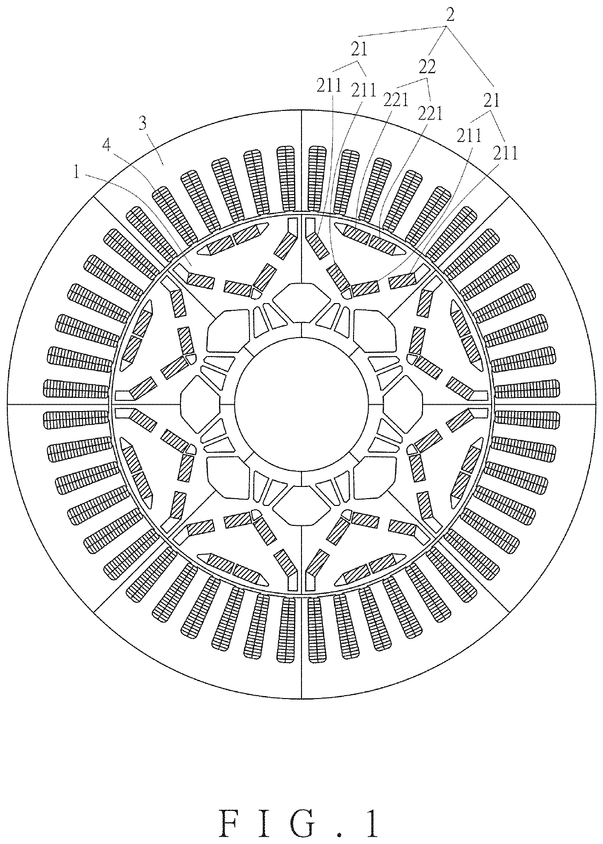
[0022]As shown in FIG. 1, a rotor structure for a motor according to an embodiment of the present invention comprises a rotor core 1. The rotor core 1 has a plurality of magnetic member units 2 arranged around the periphery of the rotor core 1. The motor of this embodiment further includes a stator core 3. The stator core 3 covers the rotor core 1. The stator core 3 has a plurality of stator windings 4 arranged annularly. The stator windings 4 correspond to the magnetic member units 2.

[0023]Each magnetic member unit 2 of the rotor core 1 includes two first magnetic members 21 and a second magnetic member 22. The two first magnetic members 21 are obliquely arranged in a V shape relative to the center of the rotor core 1. The second magnetic member 22 extends transversely between the two first magnetic members 21. As shown in FIG. 1, each first magnetic...


PUM


Abstract

A motor and a rotor structure thereof are disclosed. The rotor structure includes a rotor core. The rotor core has a plurality of magnetic member units arranged around a periphery of the rotor core. Each magnetic member unit includes two first magnetic members and a second magnetic member. The two first magnetic members are obliquely arranged in a V shape relative to a center of the rotor core. The second magnetic member extends transversely between the two first magnetic members. Each first magnetic member has at least two permanent magnets that are arranged obliquely. The motor further includes a stator core covering the rotor core. The stator core has a plurality of stator windings arranged annularly. The stator windings correspond to the magnetic member units. The rotor structure has high structural strength, and the phenomenon of stress concentration is less obvious when the motor is running.

Description

FIELD OF THE INVENTION[0001]The present invention relates to a motor and a rotor structure thereof, and more particularly to a rotor structure with high strength, which can withstand higher speeds when the motor is running.BACKGROUND OF THE INVENTION[0002]Referring to FIG. 4, a conventional motor for an electric vehicle (the motor is used for Lexus LS600h) comprises a rotor A and a corresponding stator B. The rotor A has a plurality of magnetic member units A1 arranged annularly. The stator B has a plurality of stator windings B1 corresponding to the magnetic member units A1. Each magnetic member unit A1 includes two first magnetic members A11 and a second magnetic member A12. The two first magnetic members A11 are obliquely arranged in a V shape relative to the center of the rotor A. The second magnetic member A12 extends transversely between the two first magnetic members A11. Each of the first magnetic members All and the second magnetic member A12 is an elongated permanent magne...

Claims


Application Information

Patent Timeline
IPC IPC(8): H02K1/27H02K21/14
CPCH02K1/276H02K21/14Y02T10/64H02K1/2766
Inventor HSIEH, MIN-FUTSAI, MI-CHINGSHIH, KAI-JUNGCACERES VERA, LUCIO JOSE FERNANDOCHEN, GUAN-MING
Owner NAT CHENG KUNG UNIV
Why Eureka
Try Eureka