
Enclosed x-ray chopper wheel

a technology of enclosed chopper wheel and x-ray backscatter instrument, which is applied in the direction of instruments, material analysis using wave/particle radiation, and handling using diaphragm/collimeter, etc. it is impractical to construct x-ray backscatter instruments with enough shielding to completely eliminate x-ray energy, and tungsten is an expensive specialty metal. , to achieve the effect of reducing x-ray energy, reducing scattered x-

Pending Publication Date: 2022-09-08
VIDERAY TECH INC
View PDF30 Cites 1 Cited by
  • Summary
  • Abstract
  • Description
  • Claims
  • Application Information

AI Technical Summary

Benefits of technology

The patent describes how to create a device called a chopper wheel which helps reduce X-ray scattering when taking images. This is done through its structure, with certain parts designed to block out X-ray energy before it can reach the rest of the machine. By doing this, researchers hope to improve image quality and make sure that only relevant materials are being exposed to X-rays during medical imaging procedures.

Problems solved by technology

The technical problem addressed in this patent is how to effectively shield x-ray backscatter instruments from the x-ray energy that escapes from the instrument, while still allowing the operator to safely use it. The challenge is particularly difficult with portable handheld instruments, where the operator is in close proximity to the instrument and may receive more x-ray energy than allowed by regulations. The patent discusses the use of tungsten and tungsten alloys as shielding materials, but the high cost of tungsten makes it difficult to manufacture the housing of the instrument from this material.

Method used


Image

  • Enclosed x-ray chopper wheel
  • Enclosed x-ray chopper wheel
  • Enclosed x-ray chopper wheel

Examples


Embodiment Construction

[0020]This invention is not limited in its application to the details of construction and the arrangement of components set forth in the following description or illustrated in the drawings. The invention is capable of other embodiments and of being practiced or of being carried out in various ways. Also, the phraseology and terminology used herein is for the purpose of description and should not be regarded as limiting. The use of “including,”“comprising,” or “having,”“containing”, “involving”, and variations thereof herein, is meant to encompass the items listed thereafter and equivalents thereof as well as additional items.

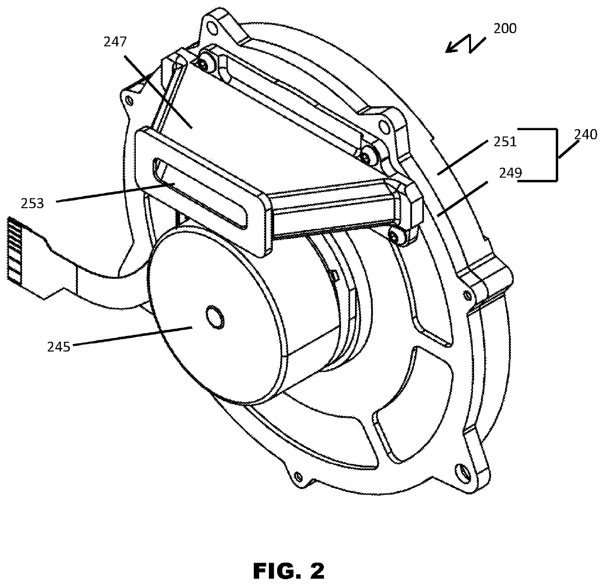
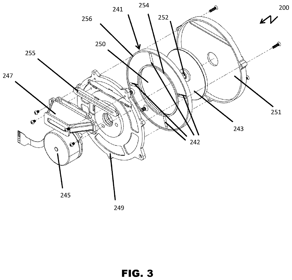
[0021]Referring now to FIG. 2, a chopper wheel assembly 200 is illustrated in accordance with some embodiments. The chopper wheel assembly 200 includes a housing 240, a drive motor 245, and a pre-collimator 247. The housing 240 includes a source-side housing 249 and a target-side housing 251. The pre-collimator 247 includes a source-side opening 253. A chopper ...


PUM


Abstract

A chopper wheel assembly includes a collimator configured to narrow an x-ray beam, a chopper wheel has a planar surface configured to face in a direction of the collimator and a housing configured to receive the chopper wheel. The chopper wheel includes a central axis, a plurality of slits in the planar surface, a first projection extending from the planar surface in a direction of the collimator and a second projection extending from the planar surface in the direction of the collimator. The slits extend in radially-outward direction relative to the central axis. The first projection is located radially outward of the plurality of slits and the second projection is located radially inward of the plurality of slits. Each projection is provided for 360 degrees about the central axis. The housing includes an interior wall including a first groove configured to receive the first projection and a second groove configured to receive the second projection with the chopper wheel received within the housing.

Description


Claims


Application Information

Patent Timeline
Owner VIDERAY TECH INC
Features
  • Generate Ideas
  • Intellectual Property
  • Life Sciences
  • Materials
  • Tech Scout
  • Unparalleled Data Quality
  • Higher Quality Content
  • 60% Fewer Hallucinations
Learn More