Gas sensor

a technology of gas sensor and crimp portion, which is applied in the field of gas sensor, can solve the problems of insufficient strength of tubular reduced diameter portion of tubular fixing portion, and inability to realize stable crimp shape, etc., and achieve the effect of suppressing lateral bulging of crimp portion, stable crimp shape, and circumferential length reduction of the rear end of the crimp portion

Pending Publication Date: 2022-09-29
NGK INSULATORS LTD
View PDF0 Cites 0 Cited by
  • Summary
  • Abstract
  • Description
  • Claims
  • Application Information

AI Technical Summary

Benefits of technology

[0014]A case will be considered in which no cutout is formed in part of the crimp portion in the circumferential direction. In this case, when the crimp portion is crimped, the rear end of the crimp portion is pushed inward in the radial direction, and thus the circumferential length of the rear end of the crimp portion decreases. As a result, an excess part of the bent portion of the crimp portion is forced in another direction, and thus, for example, lateral bulging of the crimp portion occurs. In this gas sensor, a cutout is formed in part of the crimp portion in the circumferential direction. Accordingly, even when the crimp portion is crimped and the rear end of the crimp portion is pushed inward in the radial direction, the bent portion is likely to be accommodated inside the radial direction compared with the case in which no cutout is formed. As a result, with this gas sensor, it is possible to suppress lateral bulging of the crimp portion.
[0015]According to the present invention, it is possible to provide a gas sensor capable of realizing a stable crimped shape even when the crimp portion of the housing is pressed from above during manufacture.

Problems solved by technology

However, in this gas sensor, the strength of a tubular reduced diameter portion of the tubular fixing portion may be insufficient.
As a result, a stable crimped shape may not be realized.

Method used


Image

  • Gas sensor
  • Gas sensor
  • Gas sensor

Examples


example 1

6-1. Example 1 and Comparative Examples 1 to 3

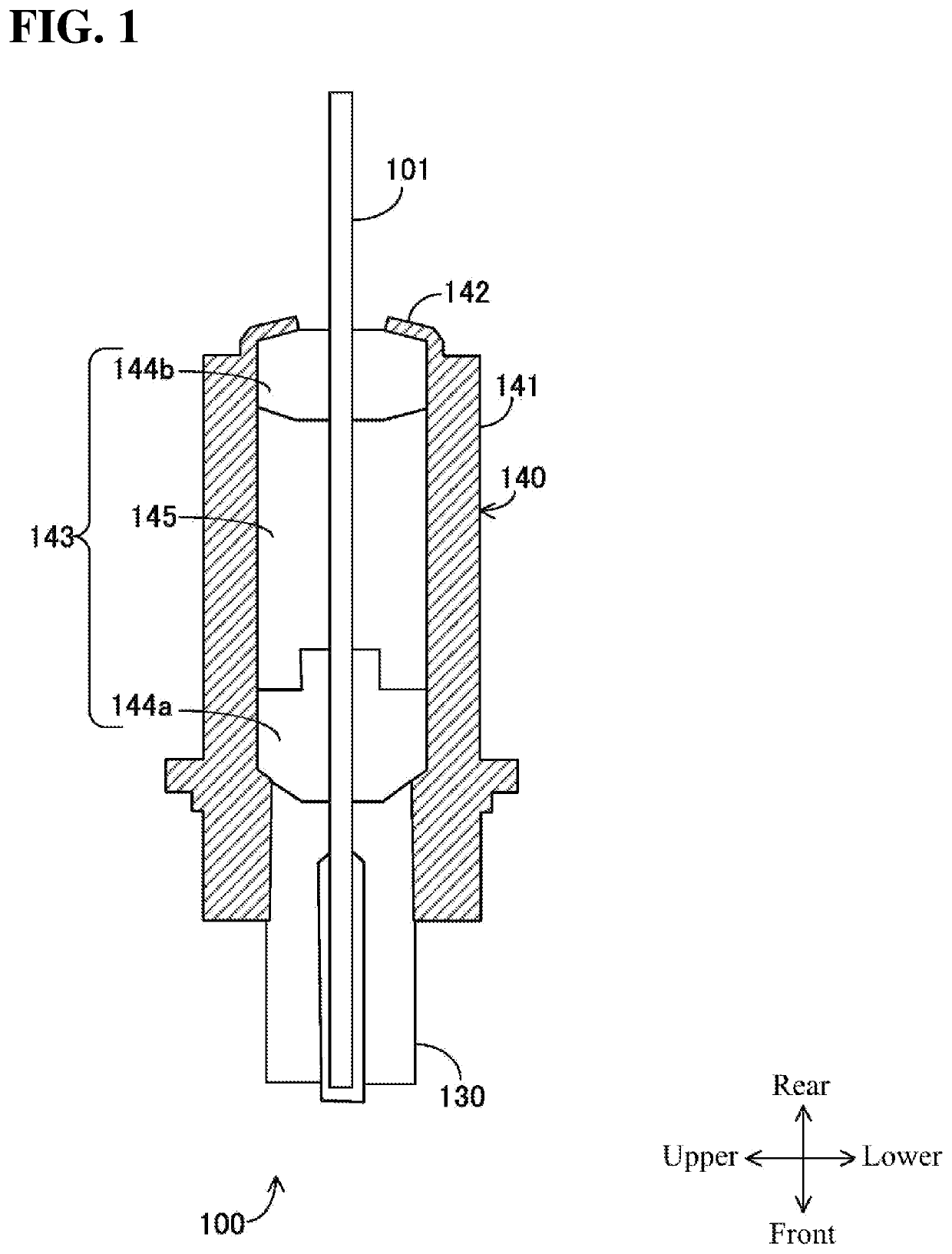
[0096]An assembly (primary assembly) equivalent to part of the gas sensor 100 shown in FIG. 1 was manufactured. Examples 1 to 3 and Comparative Examples 1 and 2 are different from each other only in terms of the shape of the crimp portion. The shape of the crimp portion in Example 1 is the shape shown in FIG. 4, the shape of the crimp portion in Example 2 is the shape shown in FIG. 8, and the shape of the crimp portion in Example 3 is the shape shown in FIG. 9.

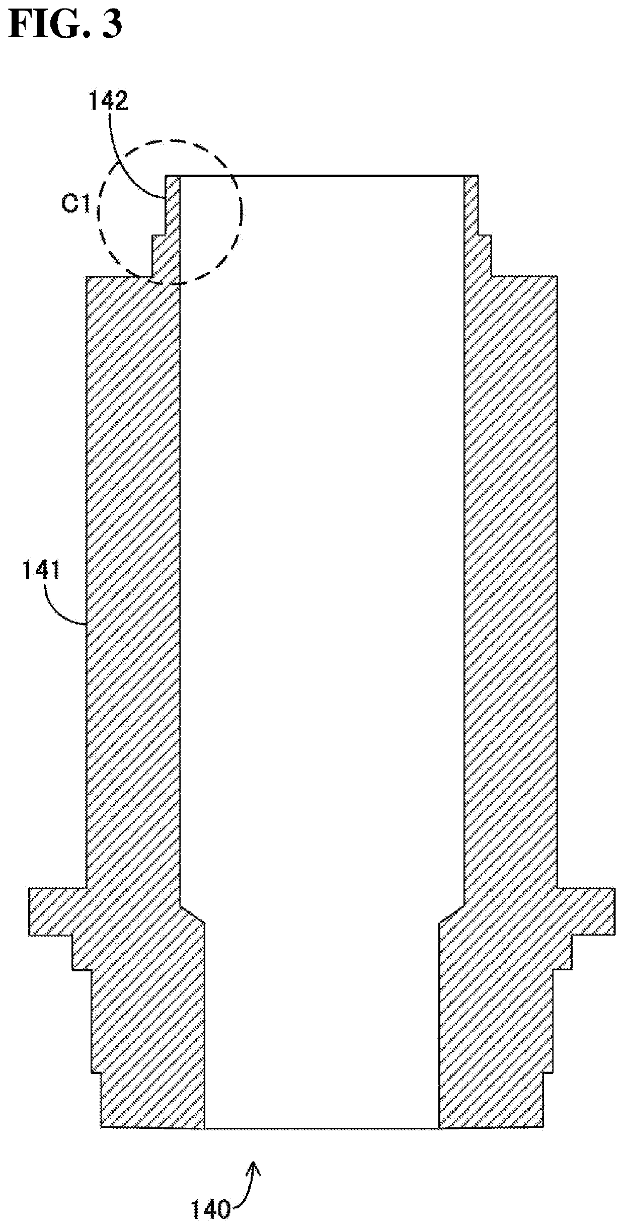
[0097]In Example 1, the thickness of the crimp portion 142 at the boundary between the crimp portion 142 and the main body 141 was 0.68 mm. The thickness of the rear end portion of the crimp portion 142 was 0.36 mm. In Example 2, the thickness of the crimp portion 142Z1 at the boundary between the crimp portion 142Z1 and the main body 141 was 0.68 mm. The thickness of the rear end portion of the crimp portion 142Z1 was 0.36 mm. In Example 3, the thickness of the crimp portion 142Z2...


PUM

PropertyMeasurementUnit
thicknessaaaaaaaaaa
length L1aaaaaaaaaa
length L2aaaaaaaaaa

Abstract

A gas sensor is capable of realizing a stable crimped shape even when the crimp portion of the housing is pressed from above during manufacture. The gas sensor includes a holding member that holds part of a sensor element. A housing accommodates the sensor element and the holding member and includes a tubular main body and tubular crimp portion. The crimp portion is located closer to a rear end than the main body, and presses, in a partially bent state, a rear end of the holding member. The crimp portion has a bending point at which a thickness changes more significantly than in each of a portion close to the main body and a portion close to the rear end, or is a point at which a degree of change in the thickness changes between the portion close to the main body and the portion close to the rear end.

Description

CROSS-REFERENCE TO RELATED APPLICATION[0001]The present application claims priority from Japanese application JP2021-049381, filed on Mar. 24, 2021, the contents of which is hereby incorporated by reference into this application.TECHNICAL FIELD[0002]The present invention relates to a gas sensor.BACKGROUND ART[0003]Japanese Patent No. 3885781 discloses a gas sensor. In this gas sensor, a sensor element is accommodated in a tubular housing. In this gas sensor, the housing and the sensor element are fixed to each other through crimping by bending a tubular fixing portion formed at a rear end of the housing.[0004]Japanese Patent No. 3885781 is an example of related art.[0005]According to the gas sensor as disclosed in Japanese Patent No. 3885781, the housing and the sensor element are fixed to each other through crimping by pressing the tubular fixing portion from above. However, in this gas sensor, the strength of a tubular reduced diameter portion of the tubular fixing portion may be ...

Claims


Application Information

Patent Timeline
Patent Type & Authority Applications(United States)
IPC IPC(8): G01N27/407
CPCG01N27/4078G01N27/4071G01N27/4162
Inventor ADACHI, HIROKISEIKE, YUYA
Owner NGK INSULATORS LTD
Why Eureka
Try Eureka