Image forming apparatus and image forming method

a technology of image forming apparatus and forming method, which is applied in the direction of electrographic process apparatus, instruments, optics, etc., can solve the problems of difficult to fabricate the belt, increase not always improve the fixing efficiency, so as to reduce the cost of the transfer belt, increase the width of the secondary transfer nip, and shorten the circumferential length of the transfer belt

Inactive Publication Date: 2010-08-05
SEIKO EPSON CORP
View PDF3 Cites 2 Cited by
  • Summary
  • Abstract
  • Description
  • Claims
  • Application Information

AI Technical Summary

Benefits of technology

[0017]Further, if the opposite roller is configured to have a large diameter, a circumferential length of the transfer belt is extended in conformity with this. If the circumferential length of the transfer belt is extended, the cost of the transfer belt is increased, or it is difficult to fabricate the belt in the first place. However, in the image forming apparatus and the image forming method of the invention, since an elastic layer is formed on a surface layer of the transfer roller, with the transfer belt being interposed between the transfer roller and the elastic surface, the diameter of the transfer roller is larger than that of the opposite roller opposite to the transfer roller. As a result, the width of a secondary transfer nip can be increased, and the circumferential length of the transfer belt can be shortened.
[0018]In addition, according to the image forming apparatus and the image forming method of the invention, since the suction surface, which sucks the transfer material, of the suction device is provided vertically underneath the transport surface, which transports the transfer material, of the transfer material transporting unit, it is possible to prevent the transfer material with creases such as a curl from being dragged between the suction device and the transfer material transporting device.

Problems solved by technology

In a fixing unit of the image forming apparatus disclosed in JP-A-2008-90114, a fixing unit is provided with two fixing devices having the first fixing device and the second fixing device to perform the fixation, but there is a problem in that even though the fixing device of two-staged configuration is used, the fixing efficiency is not always improved.
If the circumferential length of the transfer belt is extended, the cost of the transfer belt is increased, or it is difficult to fabricate the belt in the first place.

Method used


Image

  • Image forming apparatus and image forming method
  • Image forming apparatus and image forming method
  • Image forming apparatus and image forming method

Examples


Embodiment Construction

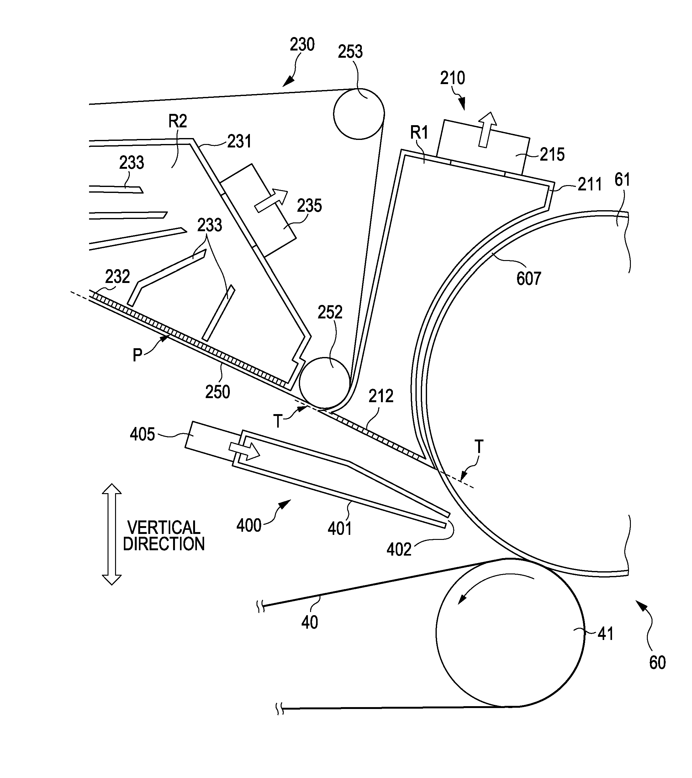
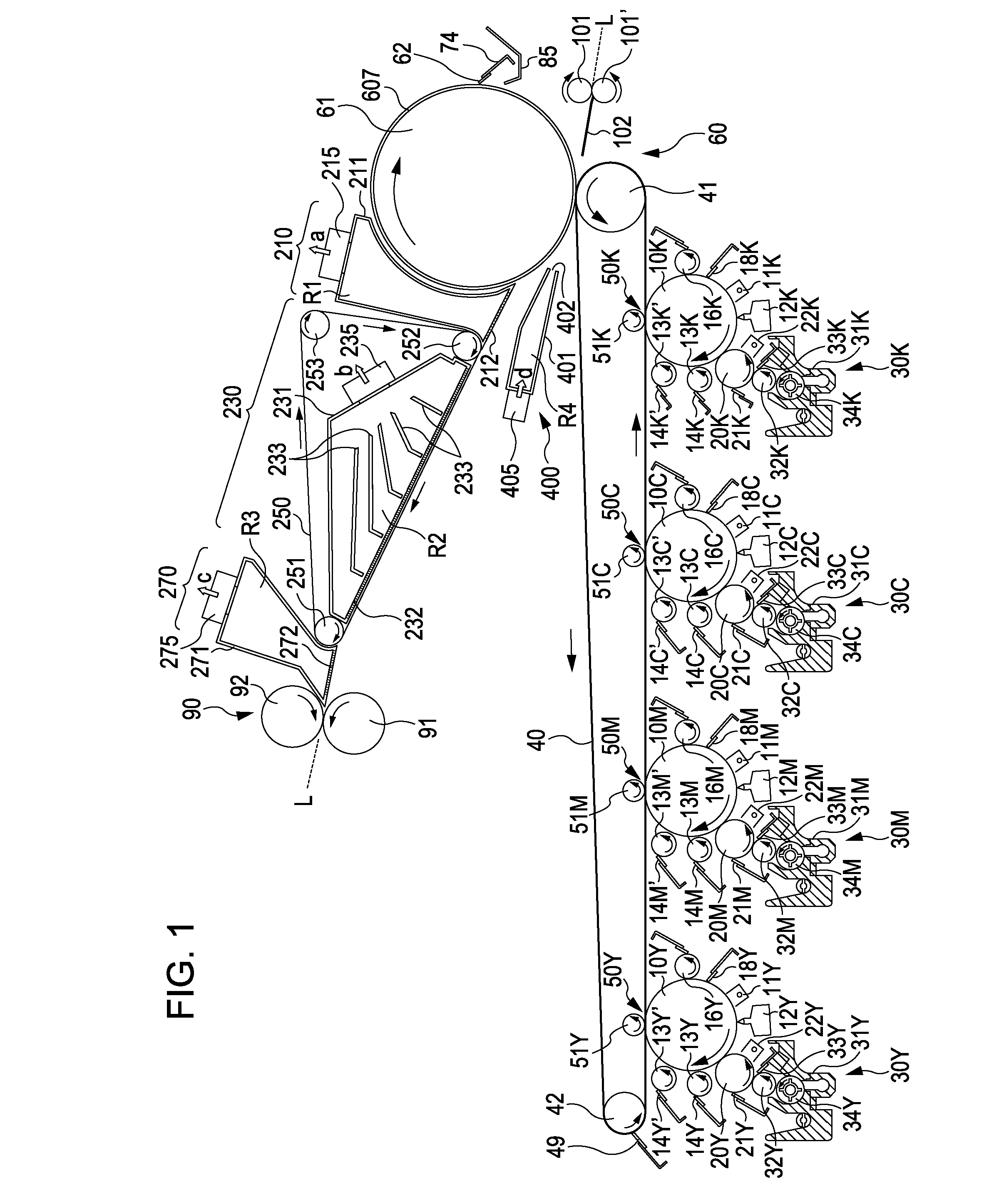
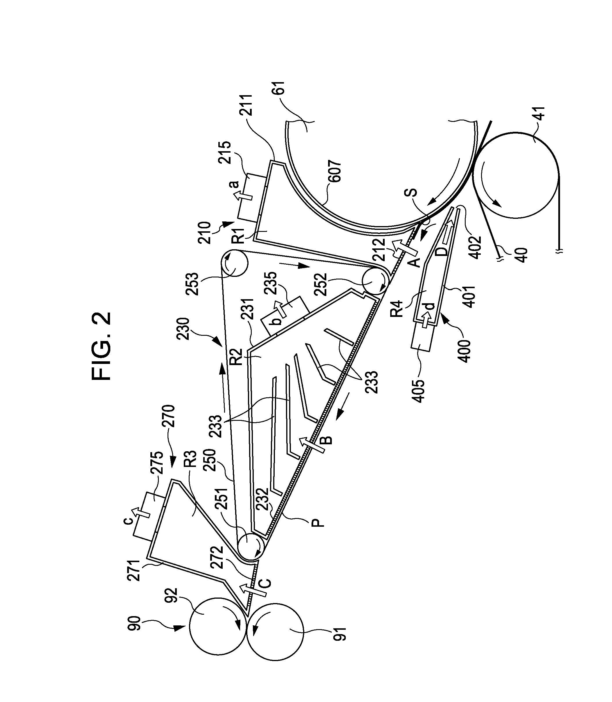
[0025]An embodiment of the invention will now be described with reference to the accompanying drawings. FIG. 1 is a diagram illustrating major constituent components constituting an image forming apparatus according to an embodiment of the invention. In an image forming unit for each color which is placed at the center portion of the image forming apparatus, developing devices 30Y, 30M, 30C, and 30K are placed at a lower portion of the image forming apparatus, and a configuration, such as transfer belt 40, secondary transfer unit (secondary transfer unit) 60, fixing unit 90 or the like, is placed at an upper portion of the image forming apparatus. In particular, since the fixing unit 90 is laid out over the transfer belt 40, it is possible to suppress the installation area of the whole image forming apparatus. In this embodiment, because of the configuration in which a transfer material such as paper, which is secondarily transferred by the secondary transfer unit 60, is sucked by a...


PUM


Abstract

An image forming apparatus and an image forming method are disclosed. The image forming apparatus includes a transfer belt that carries an image, a transfer roller that transfers the image carried on the transfer belt to a transfer material, a transfer material transporting unit that sucks a second surface, which is opposite to a first surface that is transferred the image, of the transfer material by air, and transports the transfer material along a transport surface, and a fixing unit that fixes the transfer material transported by the transfer material transporting unit.

Description

BACKGROUND[0001]1. Technical Field[0002]The present invention relates to an image forming apparatus and an image forming method which develop a latent image formed on a photoconductor by a liquid developer consisting of toner and a carrier, transfers the developer to a medium such as recording paper, and fuses and fixes the transferred toner image onto the medium to form an image.[0003]2. Related Art[0004]There are known various wet image forming apparatuses which develop a latent image by using a high-viscosity liquid developer, of which toner consisting of solid components is dispersed in a liquid solvent, to visualize an electrostatic latent image. The developer used in the wet image forming apparatus contains solid contents (toner particles) suspended in a high-viscosity organic solvent (carrier solution) consisting of silicon oil, mineral oil or cooking oil and having an electric insulating property, and the toner particles are very fine with a grain size of about 1 μm. In the ...

Claims


Application Information

Patent Timeline
Patent Type & Authority Applications(United States)
IPC IPC(8): G03G15/16
CPCG03G15/1605G03G2215/00679G03G15/657
Inventor CHIBA, SATOSHIIKUMA, KEN
Owner SEIKO EPSON CORP
Why Eureka
Try Eureka