Image forming apparatus

Inactive Publication Date: 2011-12-01
CANON KK
View PDF4 Cites 13 Cited by
  • Summary
  • Abstract
  • Description
  • Claims
  • Application Information

AI Technical Summary

Benefits of technology

[0007]The present invention has been accomplished in view of the above circumstances. A principal object of the present invention is to provide an image forming apparatus, including a contact and separation member for moving a secondary transfer member, a cleani

Problems solved by technology

However, in JP-A 2004-118019, even when the contact state and the separated state can be detected, a time required to complete the contact from the separated state or a time required to complete the separation from the contact state cannot be accurately detected.
Further, in order that the voltage to be applied to the secondary tr

Method used


Image

  • Image forming apparatus
  • Image forming apparatus
  • Image forming apparatus

Examples


embodiment 1

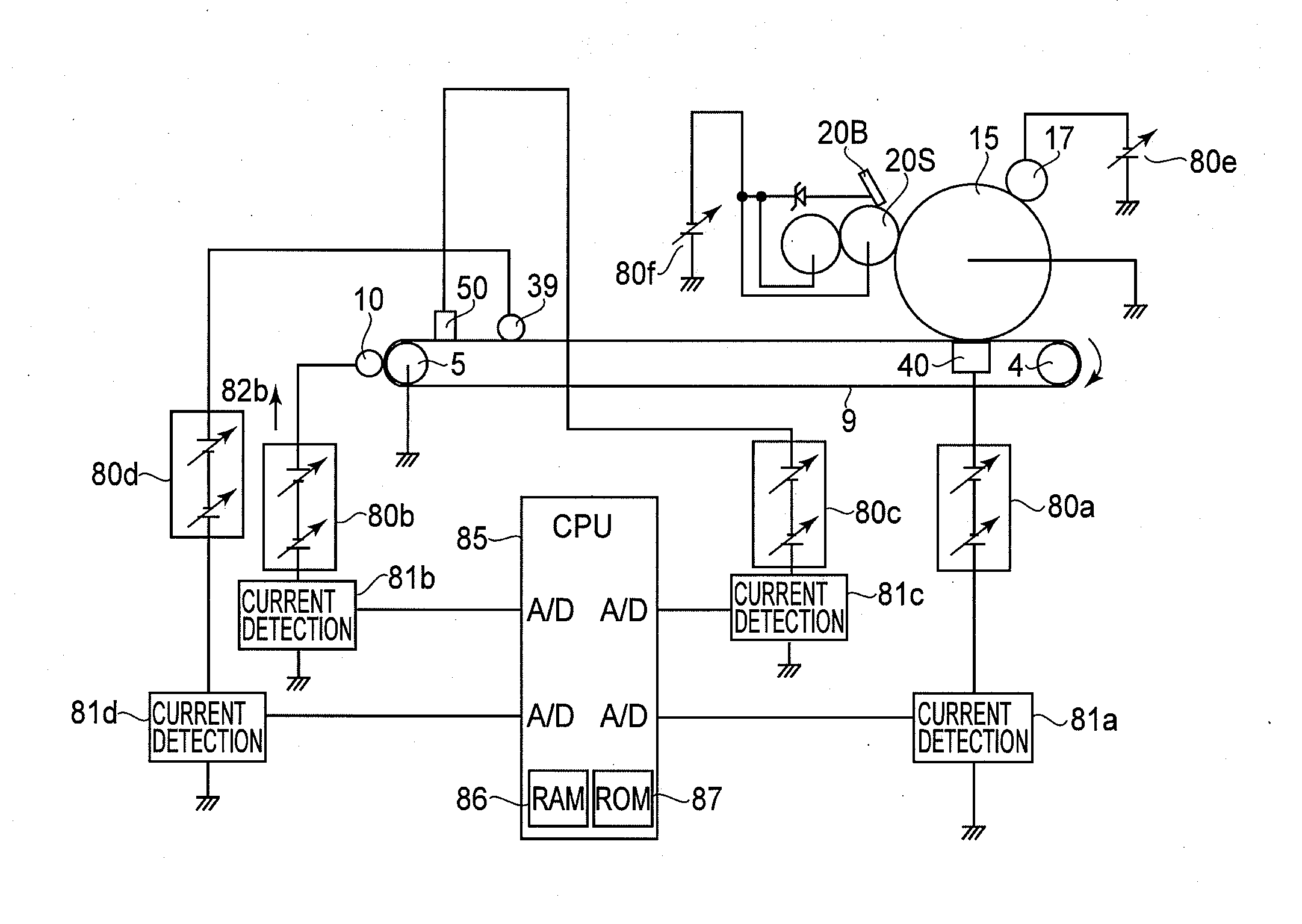
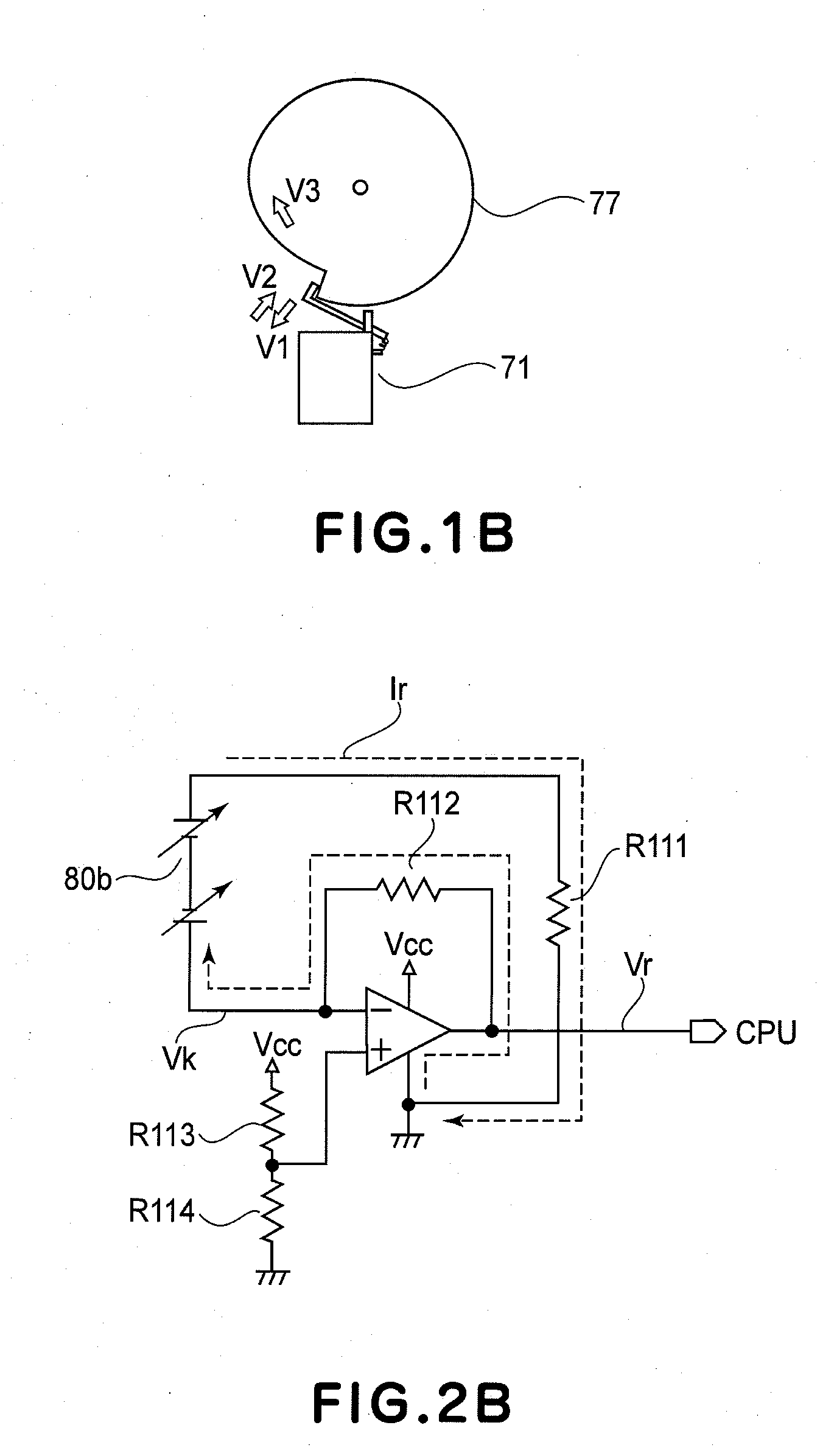
[0036]In this embodiment, the above-described circuit structure of the voltage source (FIG. 2A) and the current detecting circuit (FIG. 2B) are used. Incidentally, portions identical to those in the above-described constitution are represented by the same numerals or symbols and will be omitted from description.

[0037]FIG. 3 is a schematic view showing a contact state between the secondary transfer roller 10 and the intermediary transfer belt 9 in this embodiment. In the case where the secondary transfer roller 10 is contacted to the intermediary transfer belt 9 and the color image on the intermediary transfer belt 9 is transferred onto the recording material 2, as shown in FIG. 3, the secondary transfer roller 10 is required to be contacted to the non-image region 92. The non-image region 92 is located between a trailing (rear) end of an image region 90 and a leading (front) end of an image region 91 and is a region in which the color image is not primary-transferred at all. The non...

embodiment 2

[0046]In Embodiment 1, the image forming apparatus provided with the current detecting circuits independently for the respective voltage sources was described. In this embodiment, an image forming apparatus in which commonalty of the voltage sources and the current detecting circuits in Embodiment 1 are provided will be described.

[0047]FIG. 6A is a schematic view showing a circuit structure of the voltage source in this embodiment. In this embodiment, a point that a common voltage source 80g and a common current detecting circuit 81g are provided with respect to the secondary transfer roller 10 and the ICL roller 39 is different in constitution from Embodiment 1 but other portions of the circuit structure are similar to those shown in FIG. 2A. Further, the circuit structure of the current detecting circuit 81g is also similar to that shown in FIG. 2B.

[0048]FIG. 6B is a graph showing a change of the detected voltage Vr when the secondary transfer roller 10 is moved from the separated...

embodiment 3

[0055]An image forming apparatus in this embodiment has the same constitution as that of the image forming apparatus in Embodiment 1 except for the voltage application start timing with respect to the contact member. The circuit structure of the voltage source, the current detecting circuit, and the contact time measuring procedure and the contact operation procedure are based on those shown in FIG. 2A, FIG. 2B and FIG. 5, respectively.

[0056]First, similarly as in Embodiment 1, by executing the operations in the measuring mode of S1 to S6, the CPU 85 which is the control portion calculates the contact time of the secondary transfer roller 10 to the intermediary transfer belt 9. A shortest time, necessary for the voltage rise, calculated from a time constant or the like of the system is stored as the secondary transfer voltage rise time in the ROM 87 in advance. In Embodiment 1, the CPU 85 effected the voltage rise after the secondary transfer roller 10 is contacted to the intermedia...


PUM


Abstract

An image forming apparatus includes an image bearing member for bearing a toner image; a rotatable intermediary transfer member onto which the toner image is to be primary-transferred from the image bearing member; a contact member movable toward and away from the intermediary transfer member; a voltage applying unit for applying a voltage to the contact member; a current detecting circuit for detecting a current passing through the contact member to which the voltage is applied by the voltage applying unit; and a control portion for effecting control so that the contact member is contacted to or separated from the intermediary transfer member. The control portion is capable of executing an operation in a measuring mode in which a contact time required to bring the contact member into contact to the intermediary transfer member is calculated, based on a change in current detected by the current detecting circuit, when the contact member to which an initial voltage is applied by the voltage applying unit is contacted to the intermediary transfer member by being moved from a separated state so as to be contacted to the intermediary transfer member. The control portion brings, during image formation, the contact member into contact to a non-image region on the intermediary transfer member based on the contact time.

Description

FIELD OF THE INVENTION AND RELATED ART[0001]The present invention relates to an image forming apparatus, principally employing an electrophotographic process, such as a color laser printer, a color copying machine or a color facsimile machine.[0002]The image forming apparatus employing the electrophotographic process forms an image by developing a latent image on a photosensitive drum with toner which is a developer and then by transferring and fixing the developed latent image on a recording material such as a print sheet. In such an image forming apparatus, in order to form a color image in particular, a constitution in which toner images of a plurality of colors (yellow, magenta, cyan and black) are primary-transferred superposedly onto an intermediary transfer belt and thereafter are collectively secondary-transferred onto the recording material has been generally known. As the image forming apparatus employing the intermediary transfer belt, a rotary-type image forming apparatu...

Claims


Application Information

Patent Timeline
IPC IPC(8): G03G15/16
CPCG03G15/1605G03G15/161G03G2215/0193G03G2215/0177G03G15/167G03G15/01G03G15/16
Inventor MATSUMOTO, JUN
Owner CANON KK
Why Eureka
Try Eureka