Steering control apparatus
a control apparatus and steering technology, applied in the direction of electric steering, power driven steering, vehicle components, etc., can solve the problems of driver discomfort or unpleasantness, collision with obstacles,
- Summary
- Abstract
- Description
- Claims
- Application Information
AI Technical Summary
Benefits of technology
Problems solved by technology
Method used
Image
Examples
first embodiment
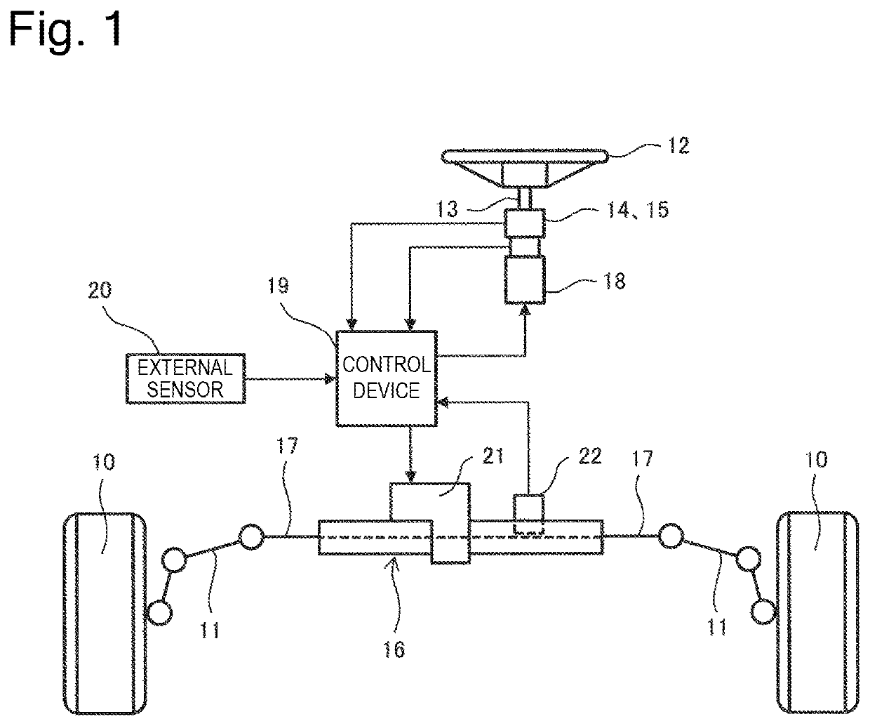
[0029]The configuration of a steer-by-wire steering control apparatus will be described before specific embodiments of the present invention will be described.
[0030]First, the steer-by-wire steering control apparatus will be described. The steer-by-wire steering control apparatus disconnects a steering operation shaft from a steering shaft, detects a rotational angle, a disturbance torque, and the like of the steering operation shaft using a rotational angle sensor, a current sensor, and the like, and controls an operation amount of a steering actuator based on these detection signals to drive the steering shaft. The configuration of a steering mechanism will be described below.
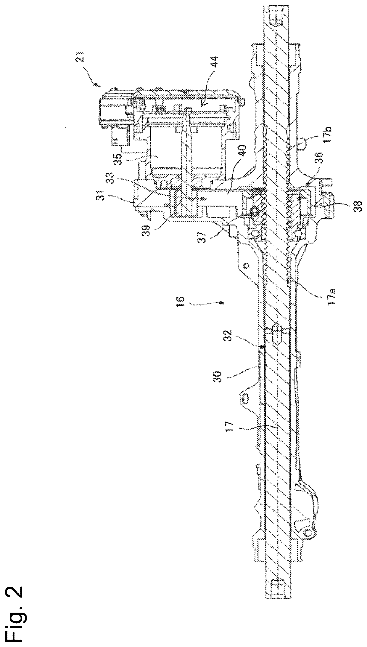
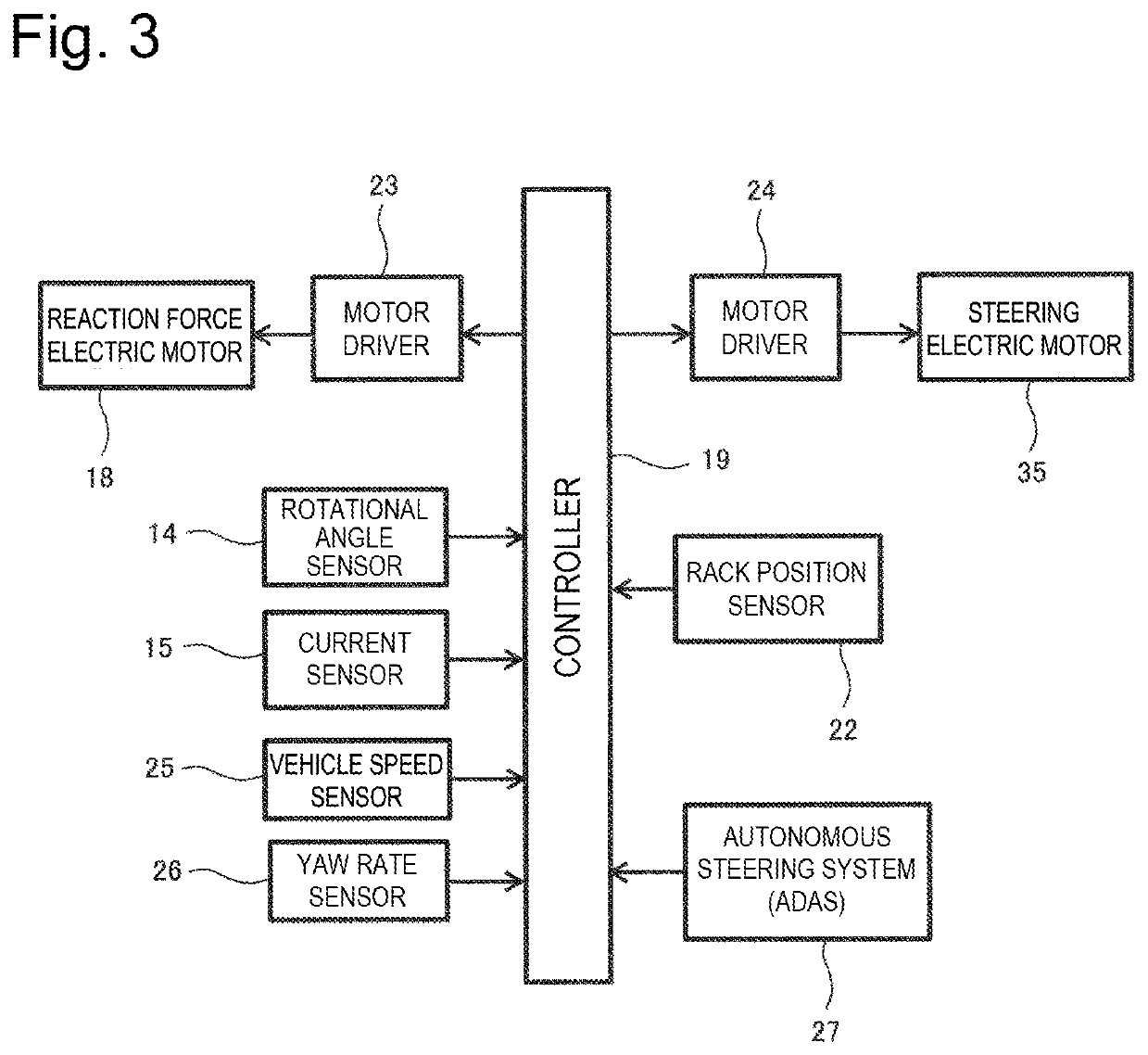
[0031]In FIG. 1, a steering target wheel 10 (or a wheel 10 of a vehicle to be turned) is configured to be steered by a tie rod 11, and this tie rod 11 is coupled with a steering shaft 17, which will be described below. Then, a steering wheel 12 is coupled with a steering operation shaft (corresponding to a st...
second embodiment
[0139]Next, a second embodiment based on the basic control flow illustrated in FIG. 6 will be described. This second embodiment is configured to correct the reaction force torque instruction value so as to reduce the mismatch between the actual steering ratio (SRact) and the setting steering ratio (SRset) based on the actual steering ratio (SRact) determined based on the reaction force motor rotational angle (θm) and the rack position (Rp) and the setting steering ratio (SRset) when a steering operation is performed on the steering wheel by the driver and the steering target wheel 10 reaches the neutral position. In the following description, a control flow thereof will be described with reference to FIG. 7.
[0140]24>>25>> Step S24 and step S25 are similar to the control steps illustrated in FIG. 6, and therefore the descriptions thereof will be omitted here. As described above, step S24 and step S25 are performed when the driver performs a steering operation on the steering wheel 12...
third embodiment
[0148]Next, a third embodiment based on the basic control flow illustrated in FIG. 6 will be described. This third embodiment is configured to correct the steering torque instruction value so as to reduce the mismatch between the actual steering ratio and the setting steering ratio based on the actual steering ratio (SRact) determined based on the reaction force motor rotational angle (θm) and the rack position (Rp) and the setting steering ratio (SRset) when a steering operation is performed on the steering wheel by the driver and the steering target wheel 10 reaches the neutral position. In the following description, a control flow thereof will be described with reference to FIG. 8.
[0149]24>>25>>26>> Step S24, step S25, and step S26 are similar to the control steps illustrated in FIG. 7, and therefore the descriptions thereof will be omitted here. As described above, these step S24, step S25, and step S26 are performed when the driver performs a steering operation on the steering ...
PUM
 Abstract
Description
Claims
Application Information
 - R&D
- Intellectual Property
- Life Sciences
- Materials
- Tech Scout
- Unparalleled Data Quality
- Higher Quality Content
- 60% Fewer Hallucinations
Browse by: Latest US Patents, China's latest patents, Technical Efficacy Thesaurus, Application Domain, Technology Topic, Popular Technical Reports.
© 2025 PatSnap. All rights reserved.Legal|Privacy policy|Modern Slavery Act Transparency Statement|Sitemap|About US| Contact US: help@patsnap.com


