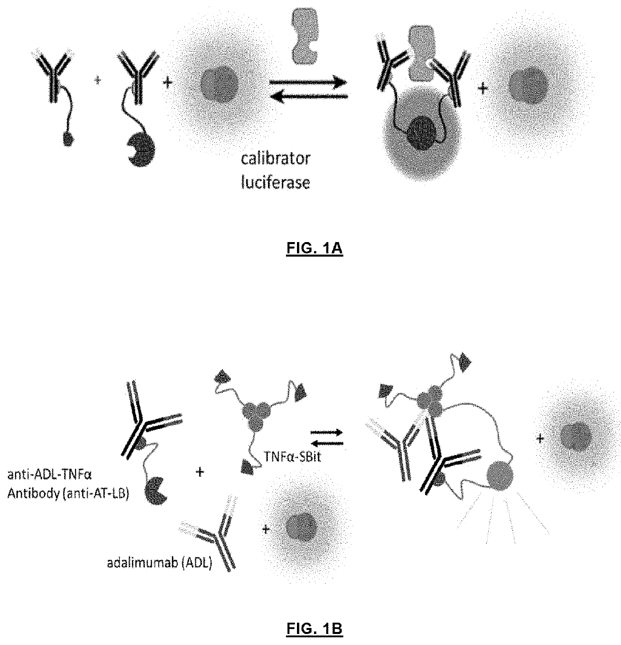
Ratiometric detection of luciferase assays using a calibrator luciferase
a luciferase and assay technology, applied in the field of bioluminescent assays, can solve the problems of difficult control of time dependence of luminescent signal, inconvenient measurement, and difficulty in quantitative measuremen
- Summary
- Abstract
- Description
- Claims
- Application Information
AI Technical Summary
Benefits of technology
Problems solved by technology
Method used
Image

Examples
example 1
Bioluminescent Sandwich Immune Assay for the Detection of Cardiac Troponin I, C-Reactive Protein and Anti-Cetuximab Antibodies
Cloning
[0040]The pET28a(+) vectors containing DNA encoding protein G-SB (pG-SB) and protein G-LB (pG-LB) were ordered from GenScript. Site directed mutagenesis to change SB sequences were carried using the QuikChange Lightning Site-Directed Mutagenesis kit (Agilent technologies) using specific primers. All cloning and mutagenesis results were confirmed by Sanger sequencing (StarSEQ). FIGS. 7, 9 and 10 show the DNA and corresponding amino acid sequences of pG-SB (variants) and pG-LB.
Protein Expression
[0041]The pET28a plasmids encoding pG-LB or pG-SB were co-transformed into E. coli BL21 (DE3) together with a pEVOL vector encoding a tRNA / tRNA synthetase pair in order to incorporate para-benzoylphenylalanine (pBPA). The pEVOL vector was a gift from Peter Schultz (Addgene plasmid #31186). Cells were cultured in 2YT medium (16 g peptone, 5 g NaCl, 10 g yeast extra...
example 1a
Sensor Design and Characterization (Cardiac Troponin I)
[0046]In order to establish a proof-of-concept, cardiac troponin I (cTnO) as a target antigen was chosen which is an important marker for cardiac damage and requires highly sensitive detection at μM concentrations. An LB fragment of split NanoLuc and an SB fragment with a Kd of 2.5 μM, respectively, were fused to protein G via a semi-flexible linker. A His-tag at N-terminus and a strep-tag at C-terminus were included to facilitate the purification of the fusion proteins. The plasmid contained a TAG amber stop codon at position 24 in protein G, and co-expression with the orthogonal tRNA synthetase / tRNA pair allowed the incorporation of the unnatural amino acid para-benzyol-phenylalanine (BPA), a photo-reactive group, at the desired position (see also: Hui, J. Z., et al., LASIC: Light Activated Site-Specific Conjugation of Native IgGs. Bioconjugate Chem. 2015, 26, 8, p. 1456-1460). The BPA incorporated protein G domain can be cros...
example 1b
Sensor Design and Characterization (C-Reactive Protein)
[0049]The assay format of example 2 was also applied for the detection of the inflammatory marker C-reactive protein (CRP). The pG-SB and pG-LB proteins were conjugated to a pair of anti-CRP antibodies C135 (mIgG2b) and C6 (mIgG2a), respectively. Following the successful photo-conjugation of antibodies with pG-SB and pG-LB and one-step nickel affinity purification, the intensiometric assays for CRP were carried out, yielding a maximal S / B ratio of 56 (FIG. 15A). Addition of the NL-mNG calibrator made the assays less fluctuant over time without influence on the detection limit and regime (FIG. 15C and FIG. 15D). The maximal ratio change of 18 and a LOD of 3 μM were achieved in the ratiometric assays by adding 2 μM of NL-mNG calibrator.
Assay Evaluation
[0050]The analytical performance of the assay was compared with a commercially available ELISA for quantification of CRP in human blood plasma. The test CRP samples were prepared at ...
PUM
| Property | Measurement | Unit |
|---|---|---|
| pH | aaaaa | aaaaa |
| pH | aaaaa | aaaaa |
| concentration | aaaaa | aaaaa |
Abstract
Description
Claims
Application Information
 - R&D Engineer
- R&D Manager
- IP Professional
- Industry Leading Data Capabilities
- Powerful AI technology
- Patent DNA Extraction
Browse by: Latest US Patents, China's latest patents, Technical Efficacy Thesaurus, Application Domain, Technology Topic.
© 2024 PatSnap. All rights reserved.Legal|Privacy policy|Modern Slavery Act Transparency Statement|Sitemap