
Vacuum nozzle system

a vacuum nozzle and nozzle technology, applied in the field of vacuum nozzle systems, can solve the problems of /b> clogging, damage to equipment, inconsistent air velocity,

Pending Publication Date: 2022-11-10
SONNYS ENTERPRISES LLC
View PDF17 Cites 0 Cited by
  • Summary
  • Abstract
  • Description
  • Claims
  • Application Information

AI Technical Summary

Benefits of technology

The invention provides a vacuum nozzle system that can effectively remove air without causing loud noise or reducing the vacuum in other nozzles. This system has improved reliability and storage capacity compared to previous devices.

Problems solved by technology

This growth and subsequent reduction of cross-sectional area leads to inconsistent air velocity.
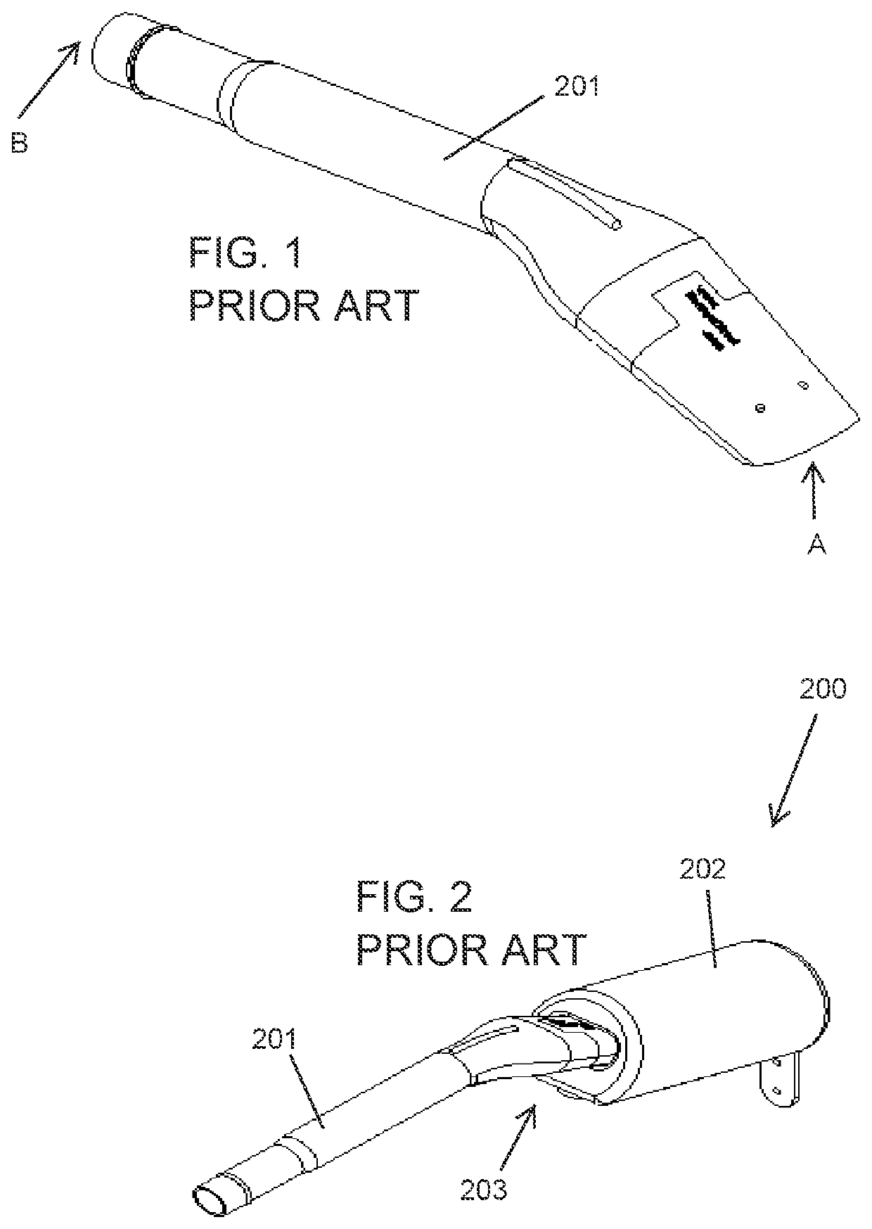
The Sonny's nozzle has vertical stiffeners near the entrance opening A that result in a blockage point that may block larger objects from going through the claw, which could possibly damage equipment and which provide for structural support of the claw 201.
The blockage point can also become a trap point for smaller objects that should be able to pass through and will cause the claw 201 to get clogged.
Furthermore, the gaps draw part of the suction power of the central vacuum system when the nozzles are stored, which in turn reduces vacuum performance on remaining nozzles of the system that are in use by users.

Method used


Image

  • Vacuum nozzle system
  • Vacuum nozzle system
  • Vacuum nozzle system

Examples


Embodiment Construction

[0029]In all the figures of the drawing, sub-features and integral parts that correspond to one another bear the same reference symbol in each case.

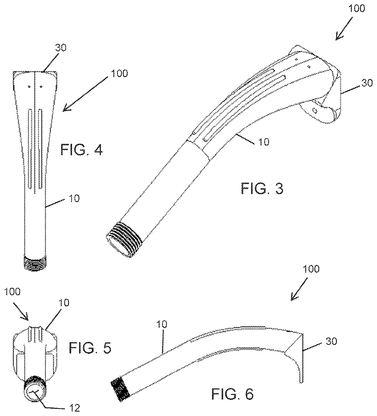
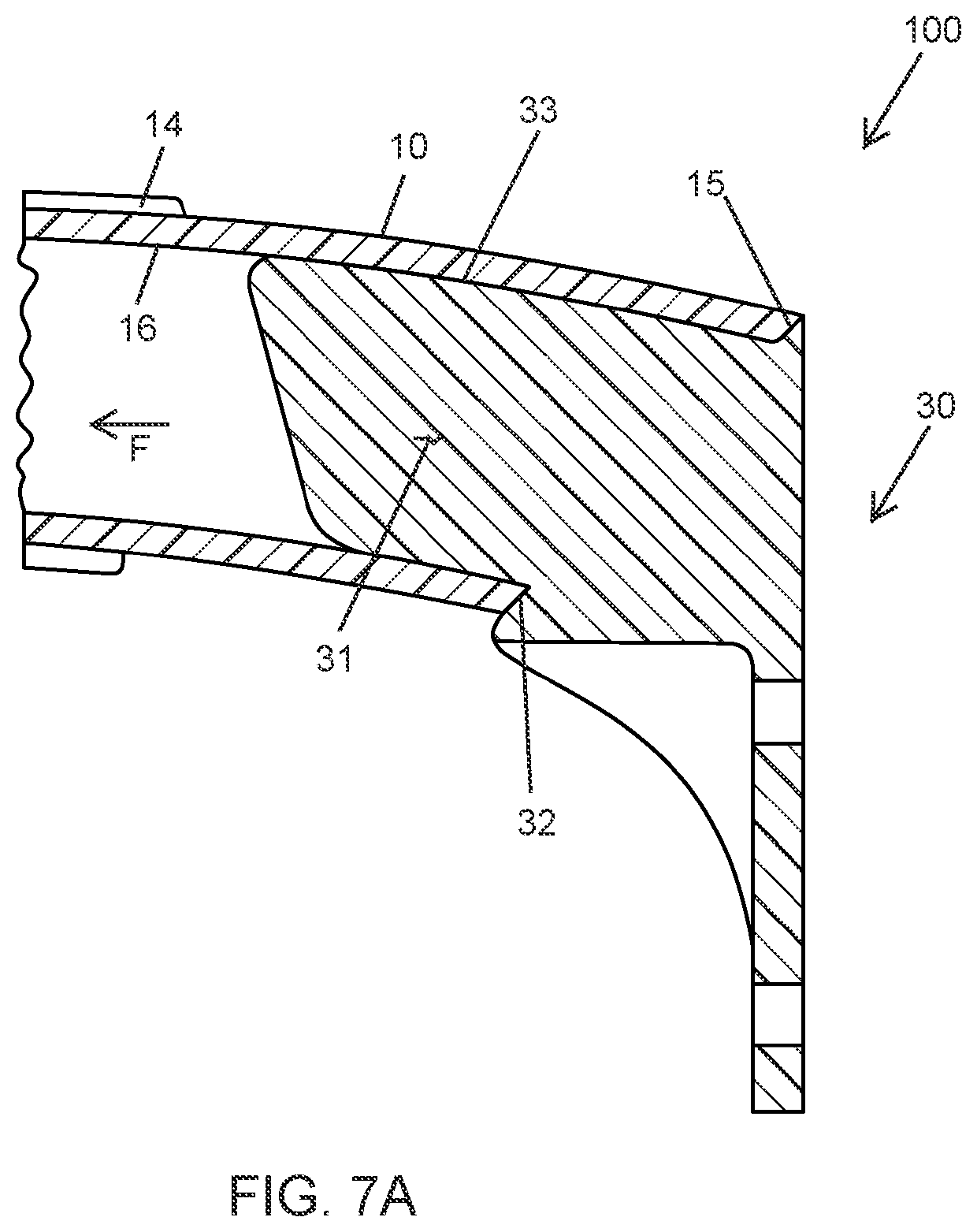
[0030]Referring now to the figures of the drawings in detail and first, particularly, to FIGS. 3-10, there is shown a vacuum claw or nozzle 10 for a vacuum claw system 100. The vacuum claw 10 has an inlet opening 11 and an exit opening 12 for connection to a vacuum hose that is connected to a central vacuum system. The inlet opening 11 has a circumferential end surface 15 that is an end of the claw 10 and delimits the inlet opening 11. The claw 10 has a curved portion 13 that extends along a longitudinal direction of the claw 10 from the inlet opening end of the claw 10 when viewed from the side. The claw 11 is provided with external ribs 14 extending along the curved portion 13. The external ribs 14 are provided on the inside and outside of the curve of the curve portion 13. The provision of the external ribs 14 eliminates the need for ...


PUM


Abstract

A vacuum nozzle system has a vacuum nozzle with an inlet opening for engaging a surface to be vacuumed and an outlet opening for connection to a vacuum supply hose. The inlet opening is delimited by a circumferential end face. The nozzle defining a vacuum flow direction from the inlet opening to the outlet opening. A holder bracket has a holder for holding the nozzle. The holder is disposed downstream of the end face in a vacuum flow in the vacuum flow direction when the nozzle is in a retained position on the holder bracket.

Description

BACKGROUND OF THE INVENTIONField of the Invention[0001]The invention relates, generally, to a vacuum nozzle system for a central vacuum system.[0002]Vacuum claws or suction nozzles are used in central vacuum systems in cleaning installations for vehicles to allow multiple individuals to simultaneously use respective claws to vacuum vehicles. When not in use, the claws or nozzles are placed on respective holder brackets. The central vacuum systems provide a continuous vacuum through the plumbing system so that the claws can be used simultaneously at any time. The claws are each connected to the vacuum by respective flexible / bendable hoses.Description of the Related Art[0003]As shown in FIGS. 1 and 2, designated as Prior Art, Sonny's prior claw discloses a claw and holster system 200 (Sonny's Vacuum Express Claw w / Bracket and Holster). The claw 201 has two openings: one is the entrance or inlet opening A where objects are vacuumed and the other is an exit opening B where a vacuum hose...

Claims


Application Information

Patent Timeline
Patent Type & Authority Applications(United States)
IPC IPC(8): A47L9/02A47L9/00A47L5/38
CPCA47L9/02A47L9/0009A47L5/38
Inventor FAZIO, PAULANALETTO, ANTHONYGUZMAN, DAVIDDOTY, MICHAEL
Owner SONNYS ENTERPRISES LLC
Learn More