Batting practice device

a technology of batting practice and ball bat, which is applied in the field of batting practice devices, can solve the problems of not allowing a batter to practice hitting a moving ball, affecting the ability of batters to hit balls, so as to prevent substantial movement of the bottom

Inactive Publication Date: 2000-02-15
BETTENCOURT JR MANUEL J
View PDF15 Cites 16 Cited by
  • Summary
  • Abstract
  • Description
  • Claims
  • Application Information

AI Technical Summary

Benefits of technology

The present invention overcomes these problems by providing a pole that is longer than the height of the pitcher, but is not permanently mounted in the ground. The pitcher prevents substantial movement of the bottom of the pole by placing a foot in an anchoring loop provided at the bottom of the pole. The pole is completely portable and no permanent ground mount is required.

Problems solved by technology

Developing the necessary coordination to hit a baseball can take considerable time.
Using a tee develops basic hand-eye coordination, but does not allow a batter to practice hitting a moving ball.
Ordinarily this would quickly fatigue the pitcher.
This solution compromised the portability of the device and limited the pitcher's control of the movement of the ball.
This prevented use of the ball in other applications, and also did not allow inexpensive replacement of the ball with standard baseballs.
Replacement is important because the ball will become damaged or worn after repeated use.

Method used


Image

  • Batting practice device
  • Batting practice device
  • Batting practice device

Examples


Embodiment Construction

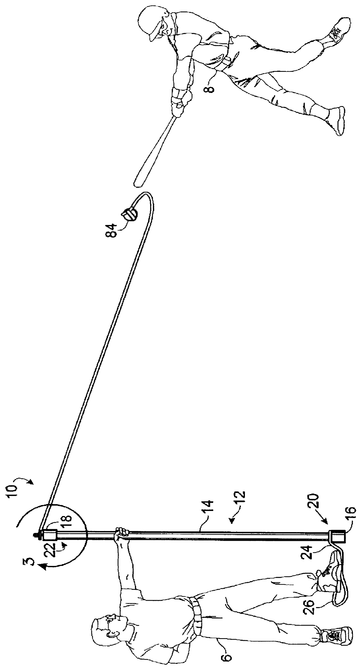
FIG. 1 shows a pitcher 6 and batter 8 using the batting practice device 10 of the present invention. A pole 12 forms the vertical support of device 10. Pole 12 can be a solid shaft made of plastic, metal, or wood, but preferably pole 12 comprises a hollow tube or pipe 14, with first and second caps 16, 18 attached to first and second ends 20, 22 of tube 14, respectively. Tube 14 and caps 16,18 can be made of metal, or preferably, durable plastic such as polyvinyl chloride (PVC). Pole 12 should be longer than the height of the pitcher, and is typically longer than 6 feet.

Anchor 26 is attached to first end 20 of tube 14. Anchor 26 limits lateral movement of first end 20 of tube 14 with respect to the ground in a manner that requires no part of the invention to be inserted or mounted in the ground. In the preferred embodiment anchor 26 comprises a loop of rope or cord knotted at 24 to the first end of tube 14. Of course, anchor 26 can be made of rope, cord, leather, or any similar mate...


PUM


Abstract

A batting practice device for use by a person acting as a pitcher and another person acting as a batter. A pole has a first end placed on the ground and a second end held substantially vertically. The pole is longer than the height of the pitcher, but is not permanently mounted in the ground. The pitcher prevents substantial movement of the first end of the pole by placing a foot in an anchoring loop provided at the first end of the pole. A line is operatively attached, via a freely rotating mount, to the second end of the pole. The line has a swivel connection to prevent twisting of the line. The line is operatively connected to a ball via a ball harness. The ball harness has two straps sewn together, with the ends of the respective straps having loops for receiving one end of the line. Various sizes of conventional balls can be easily inserted and removed from the ball harness.

Description

The present invention relates generally to devices for practicing sporting skills. More specifically, the present invention relates to a batting practice device.For many sports it is important for a player to develop hand-eye coordination. This is especially true in baseball where a batter must hit a fast-moving ball with a bat. Developing the necessary coordination to hit a baseball can take considerable time. Over the years, various methods have been developed to teach this skill. One method includes placing a ball on a stationary pole or tee, whereupon the batter attempts to hit the ball off the tee. Using a tee develops basic hand-eye coordination, but does not allow a batter to practice hitting a moving ball.Another method uses a ball permanently fastened to the first end of a rope. A "pitcher" holds the second end of the rope and swings the ball around in a circle. The batter stands outside the orbit of the moving ball and attempts to hit the ball with the bat. The second end ...

Claims


Application Information

Patent Timeline
Patent Type & Authority Patents(United States)
IPC IPC(8): A63B69/00A63B43/00
CPCA63B69/0079A63B43/007A63B69/0002
Inventor BETTENCOURT, JR., MANUEL J.
Owner BETTENCOURT JR MANUEL J
Why Eureka
Try Eureka