Athletic shoe

a technology for athletic shoes and shoes, applied in the field of athletic shoes, can solve the problems of not being able to provide the performance of gripping the lawn surface, rough green, and not being able to walk on a hard surface such as a paved path or the floor of a clubhous

Inactive Publication Date: 2000-02-29
BRIDGESTONE SPORTS
View PDF9 Cites 82 Cited by
  • Summary
  • Abstract
  • Description
  • Claims
  • Application Information

AI Technical Summary

Problems solved by technology

However, walking on a hard surface such as a paved path or the floor of a clubhouse is not comfortable and easily causes fatigue due to pushing up by the studs.
Further, the metal studs are likely to scrape grass of the green, resulting in roughed green.
However, the golf shoes using rubber studs have a drawback that they ...

Method used


Image

  • Athletic shoe
  • Athletic shoe
  • Athletic shoe

Examples


first embodiment

FIG. 6 is a plan view showing the slip prevention means of the sole of an athletic shoe (a golf shoe) according to a first embodiment of the second aspect of the present invention; and FIG. 7 is a cross-sectional view along line A--A in FIG. 6. The sole 2 of the present embodiment has a double-layer structure composed of an inner layer 4 and an outer layer 6, each of which has a single layer structure. The inner layer 4 is formed of foamed rubber (Asker-C hardness: 65.degree.), and the outer layer 6 is formed of unfoamed rubber (JIS-A hardness: 75.degree.), and therefore, the inner layer 4 is softer than the outer layer 6.

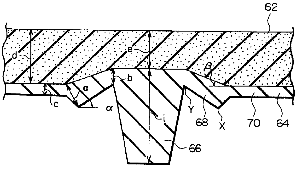
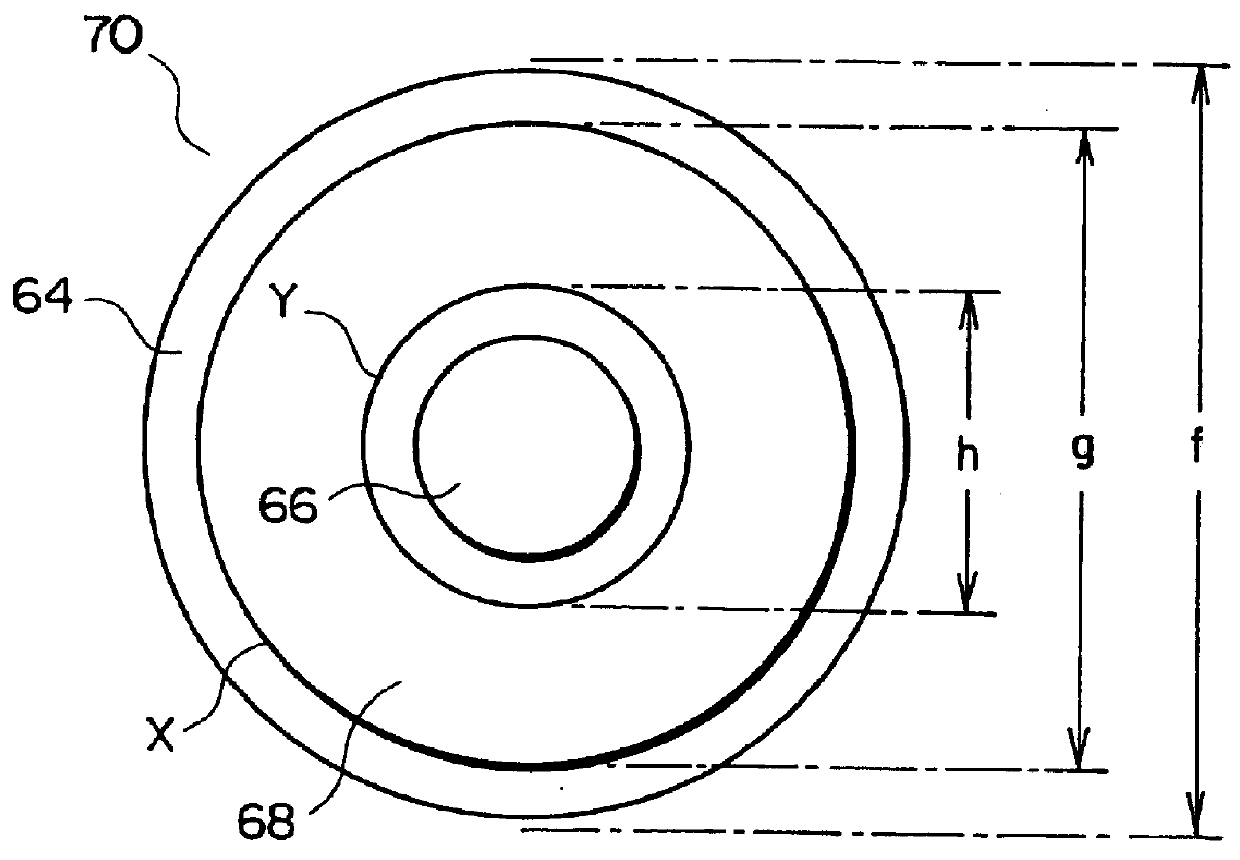
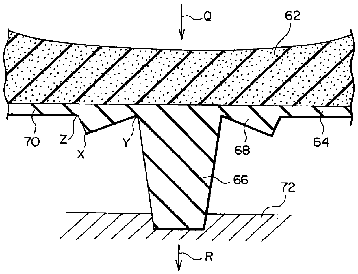
On the outer surface 8 of the sole 2 of the present embodiment are provided rubber studs serving as projections 10, which are integrally formed with the sole 2 to be projected from the outer layer 6. Further, a depression 12 is formed to surround the projection 10. The depression 12 has a circular-ring shape that is centered at the center axis of the projection 10....

second embodiment

FIG. 8 is a cross-sectional view showing the slip prevention means of the sole of an athletic shoe (a golf shoe) according to a second embodiment of the second aspect of the present invention. The sole 2 of the present embodiment is identical to the sole 2 of the first embodiment except that the thickness of the outer layer 6 is increased compared to that of the sole 2 of the first embodiment while the thickness of the inner layer 4 is decreased accordingly, and that the depression 12 is formed by depression of only the outer layer 6. Therefore, in FIG. 8, portions having the same structure as in FIG. 7 are denoted by the same reference symbols, and their descriptions will be omitted.

third embodiment

FIG. 9 is a plan view showing the slip prevention means of the sole of an athletic shoe (a golf shoe) according to a third embodiment of the second aspect of the present invention. The sole 2 of the present embodiment has a single-layer structure and is formed of butadiene rubber (JIS-A hardness: 90.degree.).

A metal stud 14 is removably attached to the sole 2 of the present embodiment. The metal stud 14 is composed of a spike body 22 and a pedestal 24 embedded in the sole 2. The spike body 22 has a base portion 16 having a thread on its outer periphery, a conical metal pin 18 projecting from the lower end of the base portion 16, and a cap portion 20 formed between the base portion 16 and the pin 18. The base portion 16 of the spike body 22 is screwed into the pedestal 24. Therefore, in the sole 2 of the present embodiment, the metal pin 18 of the metal stud 14 forms the projection 10. Further, on the outer surface 8 of the sole 2 of the present embodiment, a depression 12 is formed ...


PUM


Abstract

An athletic shoe has a sole composed of an inner layer and an outer layer that comes into contact with the ground surface. In the athletic shoe, a plurality of downward projecting projections are formed on the lower surface of the outer layer as parts of the outer layer, and a ring-shaped flange portion is formed as a part of the outer layer to surround the corresponding projection. The ring-shaped flange portion slants upward from its outer edge toward the inner edge. When a downward pressure greater than a predetermined value acts onto a portion where the projection and the corresponding flange portion are formed, the flange deforms in order to move the projection downward. In another athletic shoe, a plurality of projections is formed on the outer surface of a sole, and a depression is formed in the outer surface of the sole in the vicinity of each of the projections. The athletic shoe is excellent in terms of performance in gripping a soft ground surface such as a lawn surface and the easiness of walking on hard surfaces such as a paved path or a floor.

Description

1. Field of the InventionThe present invention relates to an athletic shoe (e.g., a golf shoe) having anti-slip projections on its sole.2. Related ArtAs anti-slip spikes provided on the soles of athletic shoes such as golf shoes, there have been employed metal studs used in so-called spike shoes and each having a metal pin of a conical shape or a truncated conical shape, rubber studs used in so-called spike-less shoes and having a cylindrical shape or a truncated conical shape, and soft spikes used in so-called soft spike shoes and having a mushroom-cap-shaped projection. The metal studs and the soft spikes are removably attached to the sole of each shoe by means of threads, whereas the rubber studs are formed integrally with the sole such that parts of the sole are projected to form the studs. Many spikes are provided on the sole mainly at the heel portion and tread portion (area between the arch portion and the toe portion) of the sole where the weight of a user acts during walkin...

Claims


Application Information

Patent Timeline
IPC IPC(8): A43C15/14A43C15/00A43C15/16A43B13/26A43B13/22A43B13/14
CPCA43B13/223A43B13/26A43C15/14A43C15/162
Inventor NIIKURA, TAKAYUKIYAMADA, TADATOSHI
Owner BRIDGESTONE SPORTS
Why Eureka
Try Eureka