

Antenna device
a technology of antenna and active element, applied in the direction of resonant antenna, elongated active element feed, radiating element structure, etc., can solve the problem of difficult to implement compact design in the mobile communication apparatus
- Summary
- Abstract
- Description
- Claims
- Application Information
AI Technical Summary
Benefits of technology
Problems solved by technology
Method used
Image

Examples
first embodiment
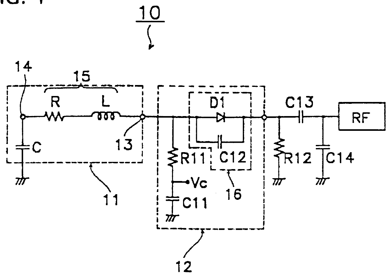
FIG. 1 is a schematic diagram of the antenna device of the present invention. An antenna device 10 includes an antenna body 11 and a frequency adjusting circuit 12.
The antenna body 11 has an equivalent circuit in which an inductive component L and a resistive component R are connected in series, and a conductor 15 having one end 13 as a feeder end and the other end 14 as a free end.
The frequency adjusting circuit 12 includes a diode D1 as a switching element, capacitors C11, C12, and resistor R11. The anode of the diode D1 is connected to the one end 13 of the antenna body 11 while being grounded via a series circuit of the resistor R11 and capacitor C11, and a control voltage Vc for controlling the diode D1 for on and off operations is coupled to the node of the resistor R11 and the capacitor C11.
The cathode of the diode D1 is connected, via capacitor C13 for adjusting the input impedance of the antenna device 10, to a radio frequency circuit RF of a mobile communication apparatus ...
second embodiment
Since in the antenna device of the second embodiment, the frequency adjusting circuit including the parallel circuit constituting the diode and the inductor is connected in series with the antenna body, the inductive component of the antenna device is changed by turning on or off the diode.
The resonant frequency of the antenna device is thus changed without changing the gain of the antenna device. More particularly, the resonant frequency with the diode turned on is set to be higher and the resonant frequency with the diode turned off is set to be lower.
FIG. 6 is a schematic diagram of a third embodiment of the antenna device of the present invention. The antenna device 30 is different from the antenna device 10 of the first embodiment (FIG. 1) in that the frequency adjusting circuit 12 is connected to the other end 14 of the conductor 15 of the antenna body 11.
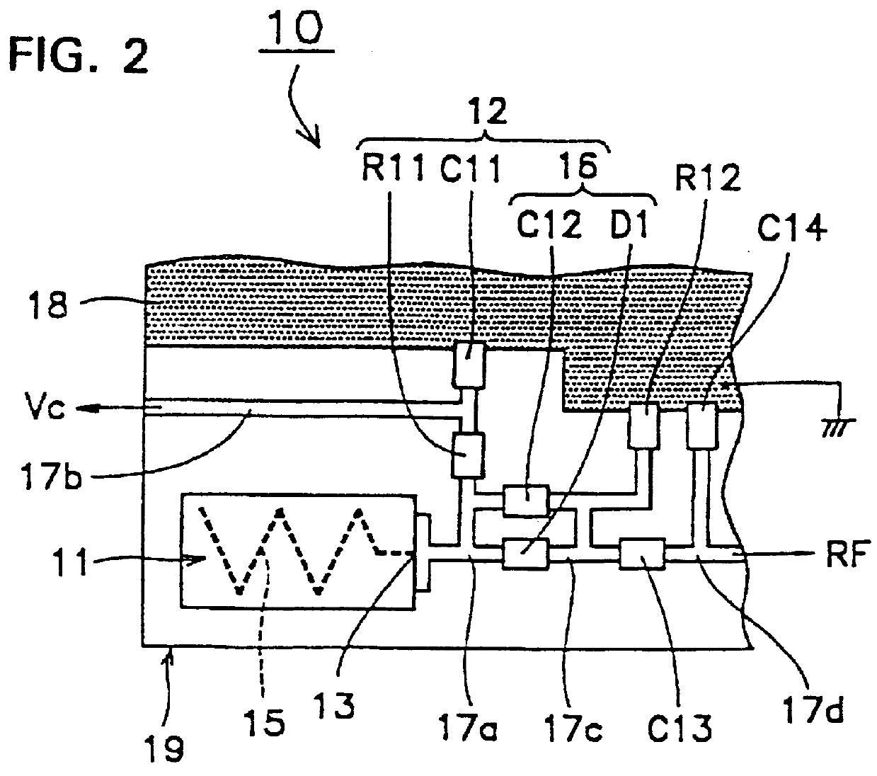
FIG. 7 is a partial top view of the antenna device 30 of FIG. 6. The antenna device 30 is produced by mounting, on a circui...
third embodiment
Since in the antenna device of the third embodiment, the frequency adjusting circuit including the parallel circuit constituting the diode and the capacitor is connected in series with the antenna body, the capacitive component of the antenna device is changed by turning on or off the diode.
The resonant frequency of the antenna device is thus changed without changing the gain of the antenna device. More particularly, the resonant frequency with the diode turned on is set to be lower and the resonant frequency with the diode turned off is set to be higher. As a result, even the antenna device itself has a narrow bandwidth, it works in a wide range of frequency, and is thus used in the mobile communication apparatus performing transmission and reception on frequencies in a wide range.
Since the antenna body and the parallel circuit constituting the diode and the capacitor are mounted on the circuit board, a compact design is implemented in the antenna device. The antenna device can thu...
PUM
 Abstract
Description
Claims
Application Information