High speed write driver for magnetic inductive write head using a half-switched H-driver

a write driver and inductive recording technology, applied in the direction of digital recording, instruments, pulse technique, etc., can solve the problems of circuit speed, not particularly fast, and large power dissipation

Inactive Publication Date: 2000-03-21
IBM CORP
View PDF10 Cites 10 Cited by
  • Summary
  • Abstract
  • Description
  • Claims
  • Application Information

AI Technical Summary

Problems solved by technology

This approach was not particularly fast and dissipated a substantial amount of power because the circuit required twice the amount of current that was delivered to the head.
This circuit is faster than the older conventional design and dissipates only half the power.
These two objectives are in conflict because switching speed through an inductive load is proportional to the voltage swing at the load; furthermore, not all the supply voltage is available to the inductive load because there are voltage drops across the "pull-up" switches, current switches, and current source.
This, and the fact that head materials and disk platter materials are continuously being improved, has lead to a drop in the inductance of the heads and the write current needed to write data to the disk.
Older generations of write drivers and heads were mostly limited by the inductance and voltage that could be induced across the head (compliance voltage).
Mismatches may occur because the times required to accomplish the swi

Method used


Image

  • High speed write driver for magnetic inductive write head using a half-switched H-driver
  • High speed write driver for magnetic inductive write head using a half-switched H-driver
  • High speed write driver for magnetic inductive write head using a half-switched H-driver

Examples


Embodiment Construction

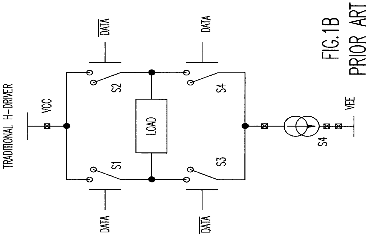
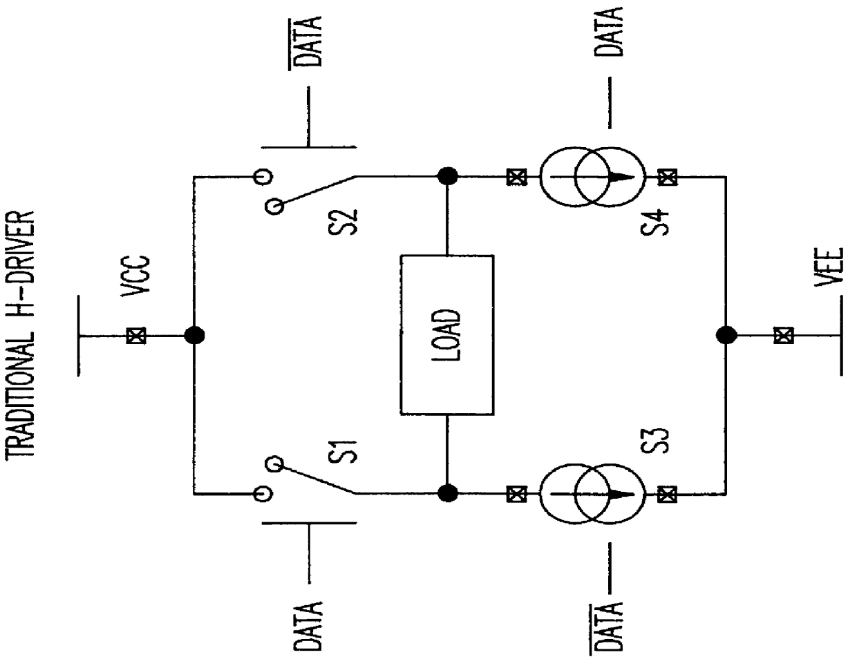
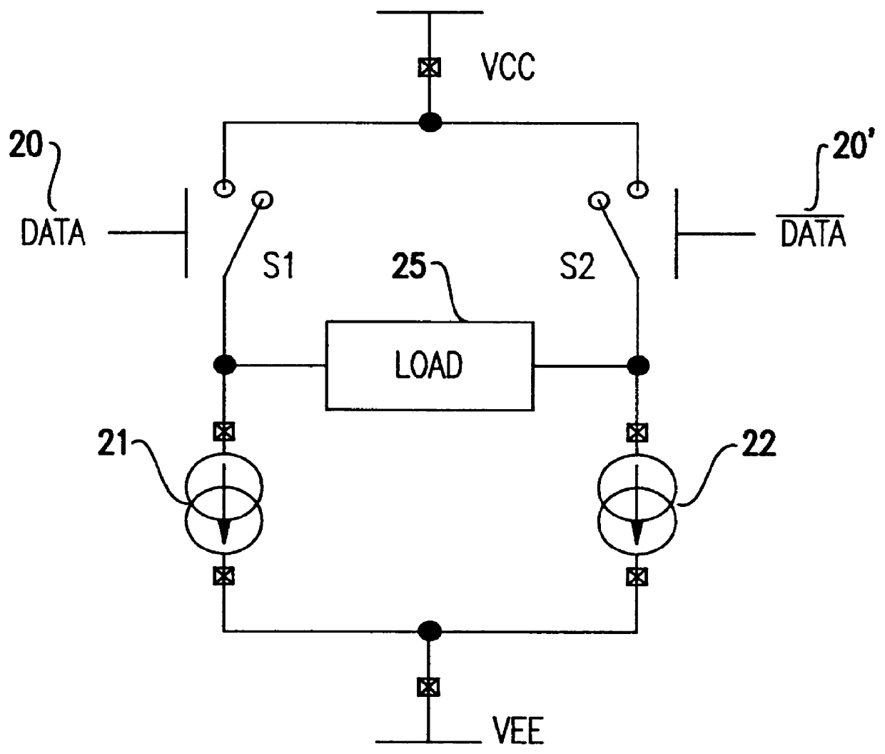
Referring now to the drawings, and more particularly to FIG. 2, there is shown a schematic of a half-switched H-driver in accordance with the present invention. The upper half of the driver is configured in the conventional manner between a supply voltage VCC and a second supply voltage VEE, with switches S1 and S2 being closed when data signal 20 and its inverse 20', respectively and alternatively, are of one polarity (e.g. high) and open when these signals are of the opposite polarity. The data signal alternates between these two polarities, and its output is therefore characterized as binary. In the conventional manner of an H-driver, alternations in the data signal, and respective alternations in closure of switches S1 and S2, cause current to flow through the inductive recording head first in one direction and then the other. In contrast to the prior art, the circuits in the bottom half of the H-driver are closed and are not switched.

The advantages of this configuration may be ...


PUM


Abstract

A write driver in an H configuration for magnetic inductive write heads characterized by having both arms in the bottom half of the driver conduct current all the time, with only the top devices being switched. In this configuration there is no need to synchronize the switching of the top and bottom halves of the H-driver. Furthermore, the device half being switched can be optimized for speed independent of the properties of the other H-driver half.

Description

1. Field of the InventionThe present invention generally relates to the field of write drivers for operating inductive recording heads. In particular it relates to a technique for increasing the speed of write drivers which use an H configuration.2. Background DescriptionA disk drive has inductive write heads that write information to the disk when current is switched through them. The switching current creates a magnetic field that is recorded on the disk medium. It is desirable to switch the head current from a positive value to a negative value (and vice versa) very fast so that data bits can be packed closer together on the disk for a given rotational speed. This leads to a higher density on the disk and allows a high data transfer rate.At one time conventional write drivers consisted of resistively-loaded emitter-coupled pairs of bipolar transistors. The transistors served to switch a constant current through the write head, which was connected between the collectors. By altern...

Claims


Application Information

Patent Timeline
IPC IPC(8): G11B5/09G11B5/012
CPCG11B5/022G11B5/09G11B5/012G11B5/4853G11B2220/2508
Inventor TANGHE, STEVEN J.
Owner IBM CORP
Why Eureka
Try Eureka