Wire clamping and twisting device for use with cordless electric screwdriver

Inactive Publication Date: 2000-03-28
SURIC MARIJAN
View PDF18 Cites 13 Cited by
  • Summary
  • Abstract
  • Description
  • Claims
  • Application Information

AI Technical Summary

Benefits of technology

It is a yet further object of the present invention to provide a wire clamping and twisting device that is easy and economical to use and make.
In addition, the inner member includes an annular groove in an outer surface thereof, and the base member includes a projection which extends into the annular groove for preventing axial movement of the inner member in the base member, while permitting rotation of the inner member in the base member.

Problems solved by technology

However, these wires can be relatively thick, and twisting multiple sets of wires during the course of a day can be tiresome and time-consuming.
As a result, the entire wires become unnecessarily twisted together, which increases the time for twisting the exposed, free ends, and does not always perform an adequate twist of the exposed, free ends of the wires.

Method used


Image

  • Wire clamping and twisting device for use with cordless electric screwdriver
  • Wire clamping and twisting device for use with cordless electric screwdriver
  • Wire clamping and twisting device for use with cordless electric screwdriver

Examples


Embodiment Construction

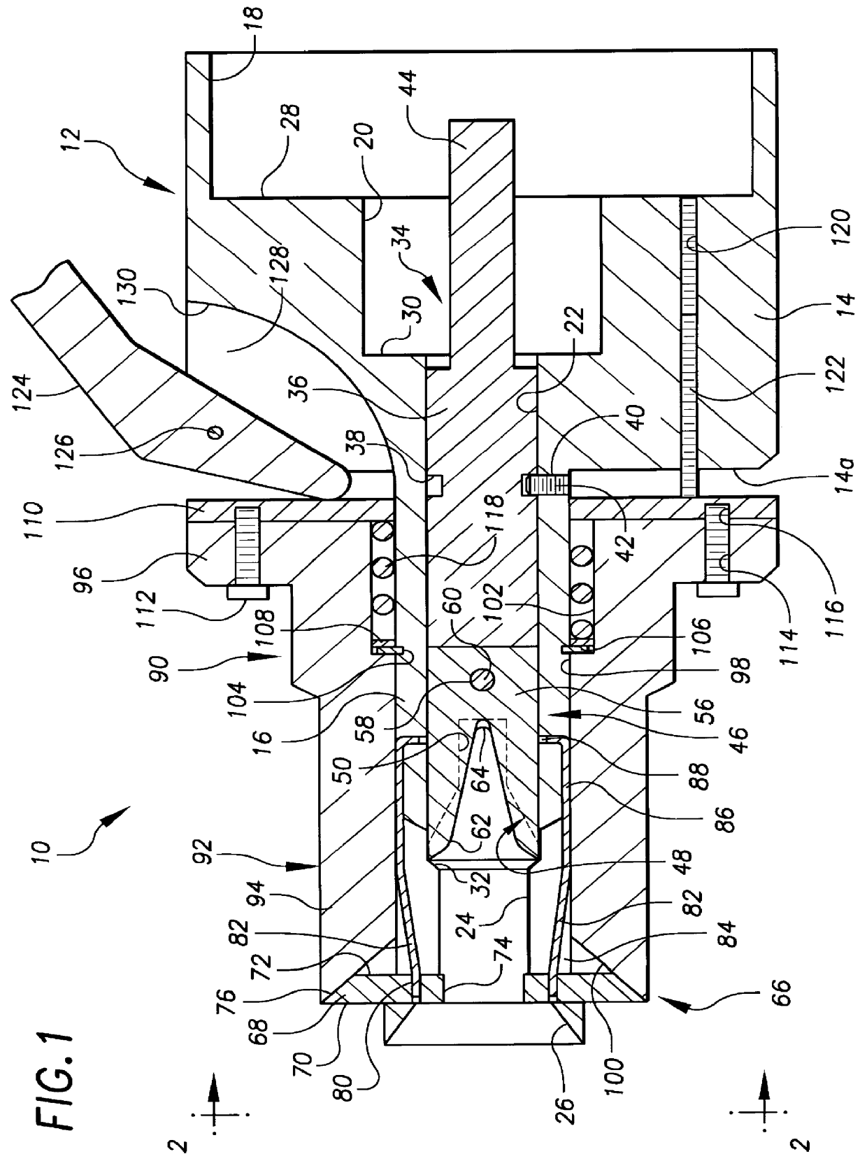
Referring to the drawings in detail, and initially to FIGS. 1-7 thereof, a wire clamping and twisting device 10 according to the present invention includes a base member 12 having a large diameter cylindrical portion 14 of a substantially constant outer diameter, and which reduces down to a small diameter cylindrical portion 16 having a smaller substantially constant outer diameter. The leftmost end of base member 12 in FIG. 1 is the front or distal end, while the rightmost end of base member 12 in FIG. 1 is the rear or proximal end thereof.

A central, longitudinal bore extends entirely through base member 12, and particularly, includes a first bore 18 at the rear end of cylindrical portion 14, which extends forward for about one-third the length of cylindrical portion 14. A second bore 20 of a lesser diameter than first bore 18 and axially aligned therewith, is in communication with first bore 18, with second bore 20 extending about another one-third of the length of cylindrical por...


PUM

PropertyMeasurementUnit
Forceaaaaaaaaaa
Tensionaaaaaaaaaa

Abstract

A wire clamping and twisting device includes a base member with a radial projection,; an inner member rotatably held in the base member and having a hexagonal shaft engageable by a cordless electric screwdriver to rotate the shaft in the base member, an inner recess for receiving the distal ends of the wires, a plate insert having a V-shaped recess extending into the inner recess, with walls of the plate insert engaging distal ends of the wires to cause the distal ends to rotate with the inner member and thereby twist the wires, and an outer surface with an annular groove which receives the radial projection of the base member for preventing axial movement of the inner member in the base member, while permitting rotation thereof; and a grasping device mounted to the base member for non-rotatably grasping portions of the wires located proximally from the distal ends of the wires during rotation of the inner member, the grasping device having opposed gripping members for gripping the proximally located portions of the wires, spring members biasing the gripping members away from each other into a non-gripping position, an outer sleeve slidably mounted on the base member and having an inner bore engaging and moving the gripping members toward each other when the outer sleeve is moved forward on the base member, and a pivotal handle for moving the outer sleeve forward on the base member.

Description

The present invention relates generally to wire clamping and twisting devices, and more particularly, is directed to a wire clamping and twisting device that will clamp two or more electrical wires and then twist the wires together in an intertwined manner.Conventionally, electricians must twist together two or more wires many times a day, and then insert a wire nut thereover. This is generally accomplished with a pair of pliers. However, these wires can be relatively thick, and twisting multiple sets of wires during the course of a day can be tiresome and time-consuming.Various wire twisting devices are known. These known wire twisting devices function to grasp the distal ends of the wires at one position thereon and then twist the wires relative to each other by a rotating action of the device. These devices assume that the proximal ends of the wires are held in one position during the twisting operation and do not move around.This is generally not true when twisting electrical wi...

Claims


Application Information

Patent Timeline
IPC IPC(8): B21F15/04B21F15/00H01R43/033H01R4/10H01R4/12
CPCB21F15/04H01R43/033H01R4/12
Inventor SURIC, MARIJAN
Owner SURIC MARIJAN
Why Eureka
Try Eureka