Method and system for graphically indicating the activity of a plurality of users within a shared data collection

a data processing and activity technology, applied in the field of collaborative computer-based systems, can solve problems such as confusion of users, difficulty in locating other users and user difficulty in determining the location of locked regions within the shared data collection

Inactive Publication Date: 2000-04-11
IBM CORP
View PDF4 Cites 113 Cited by
  • Summary
  • Abstract
  • Description
  • Claims
  • Application Information

AI Technical Summary

Problems solved by technology

However, despite the interface enhancement provided by a Graphical User Interface, having a plurality of simultaneous users within a shared data collection may confuse a user attempting to coordinate his efforts with those of other users.
A user, while knowing his own location, may have difficulty in locating other users within the shared data collection, especially if the shared data collection is large.
A user may also have difficulty determining the location of locked regions within the shared data collection.
Thus, a user may waste time searching for other users within a shared data collection or become frustrated while attempting to edit a locked region within the shared data collection.

Method used


Image

  • Method and system for graphically indicating the activity of a plurality of users within a shared data collection
  • Method and system for graphically indicating the activity of a plurality of users within a shared data collection
  • Method and system for graphically indicating the activity of a plurality of users within a shared data collection

Examples


Embodiment Construction

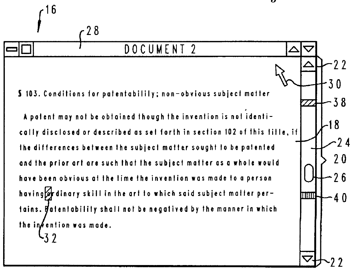
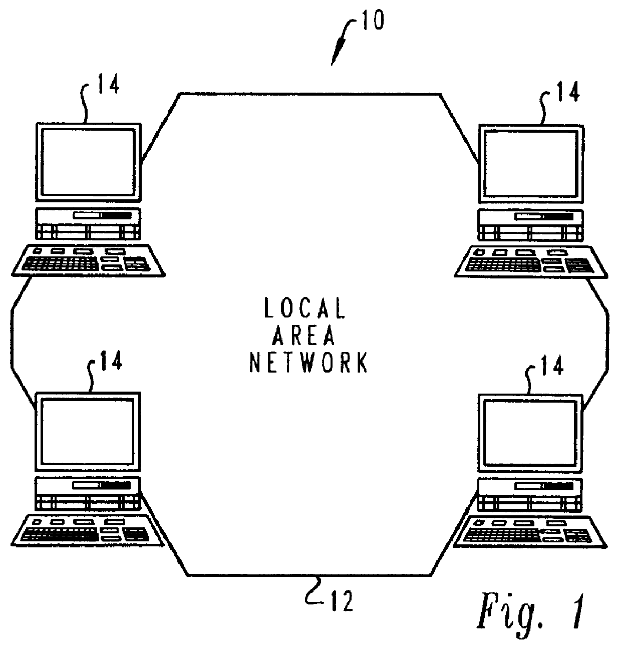
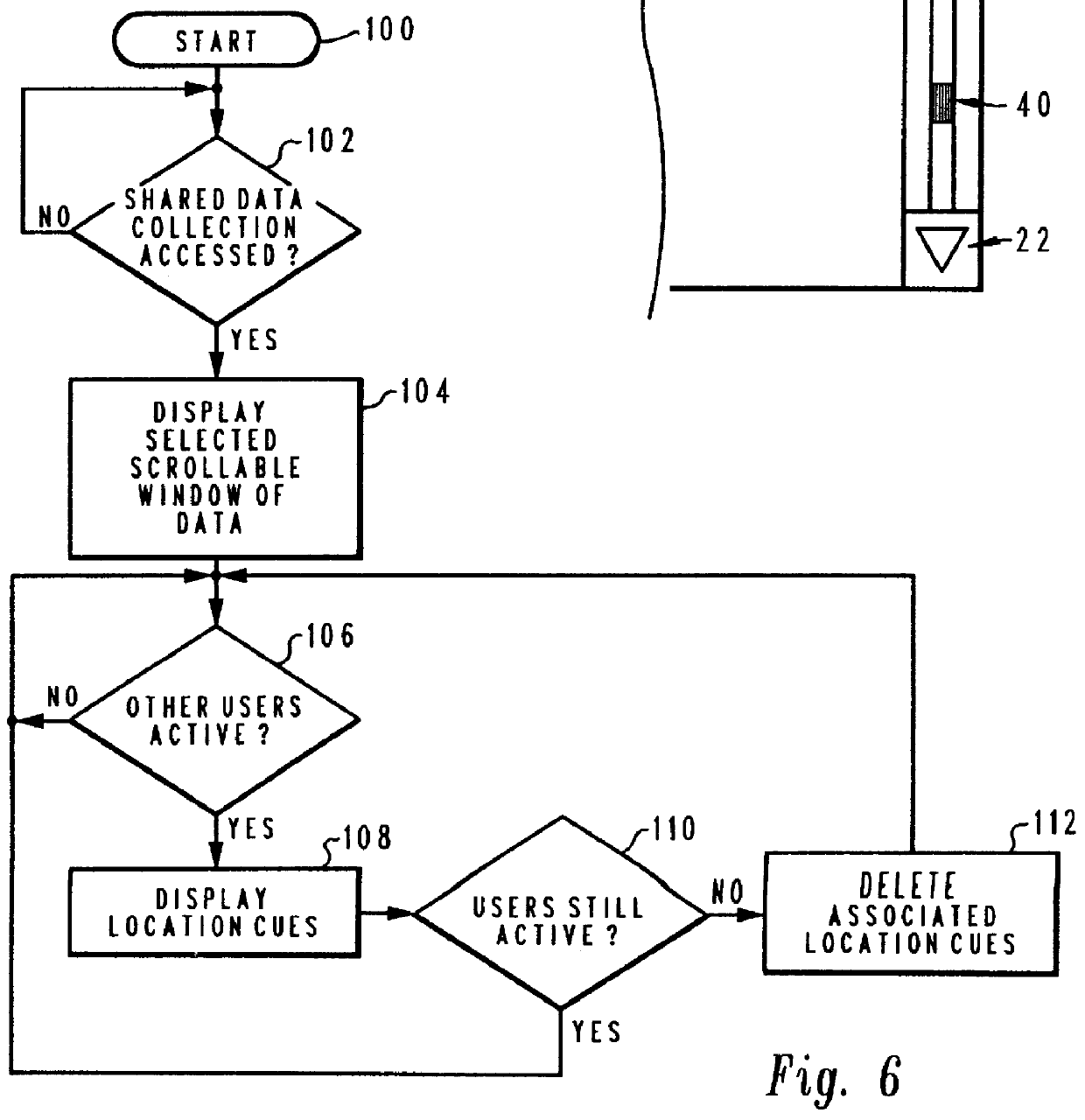
With reference now to the figures and in particular with reference to FIG. 1, there is depicted a pictorial representation of a local area network 10 which may be utilized to implement the method and system of the present invention. As is illustrated, local area network 10 supports a collaborative computer-based editing system relating to a shared data collection stored on a server. Local area network 10 provides data communication over a transmission channel 12 between a plurality of computers 14. Computers 14 within the depicted system are preferably IBM computers, such as the International Business Machines Corporation IBM Application System / 400, an IBM Personal System / 2 or other similar system. As those skilled in the art will appreciate, each computer 14 generally includes a keyboard, a video display device, and a graphical pointing device, such as a mouse. One computer 14, which may be a larger computer such as IBM Application System / 400, operates as a server for network 10 in...


PUM


Abstract

A display window is displayed in association with at least one scroll bar at a terminal associated with a first user. Along the shaft of one ore more scroll bars, a distinctive visual location cue, such as a line in a color associated with a second user, is displayed to indicate the relative location within the shared data collection of the current and historical activity of a second user. A user may temporarily prohibit manipulation of a region within the shared data collection by other users by establishing a "lock" on the region. A lock region may comprise several lines of text, a portion of a graphical object, or other data within the shared data collection. To indicate the location of lock regions, lock region location cues are also displayed along the scroll bar. In addition to indicating the location of lock regions, lock region location cues also indicate which user has established a lock region via a distinctive display attribute, preferably a distinctive color associated with the user who established the lock region. The location of a lock region is also indicated within the display area of a window by displaying the lock region with the same distinctive display attribute as the lock region location cue. In addition, when a cursor associated with a user prohibited from manipulating a lock region is located within the lock region, an aspect of the cursor, such as its shape, is altered. A preferred embodiment displays a representation of a key rather than a standard cursor to indicate to a user that his cursor is within a lock region.

Description

1. Technical FieldThe present invention relates in general to a collaborative computer-based system and in particular to data processing within a collaborative computer-based system. Still more particularly the present invention relates to a method and system for graphically indicating the activity of a plurality of users within a shared data collection within a collaborative data processing system.2. Description of the Related ArtA collaborative system may be defined as a real-time computer-based environment coordinating individual efforts toward completion of a task. The task may be a document, production schedule, computer program, product design, or any other task, solution of which is aided by the simultaneous effort of more than one person. Typically, a computer network is utilized to coordinate the work of many users. The subject of the effort of the users of the computer network is generally structured as one or more shared data collections stored in memory which is accessib...

Claims


Application Information

Patent Timeline
Patent Type & Authority Patents(United States)
IPC IPC(8): G06F3/033G06F3/048
CPCG06F3/0481
Inventor BATES, CARY LEEBLADES, JERRY ALLENDAY, PAUL R.KIEL, HARVEY GENERYAN, JEFFREY MICHAEL
Owner IBM CORP
Why Eureka
Try Eureka