Zoom lens

a zoom lens and zoom technology, applied in the field of zoom lenses, can solve the problems of increasing the difficulty of obtaining high-quality images

Inactive Publication Date: 2000-05-09
CANON KK
View PDF10 Cites 34 Cited by
  • Summary
  • Abstract
  • Description
  • Claims
  • Application Information

AI Technical Summary

Problems solved by technology

Otherwise, the ranges of variation of all aberrations during zooming and during focusing would increase greatly, thus increasing the difficulty of obtaining images of high quality.

Method used


Image

  • Zoom lens
  • Zoom lens
  • Zoom lens

Examples


numerical example 2

(Numerical Example 2)

(Numerical Example 3)

numerical example 4

(Numerical Example 4)

TABLE 1

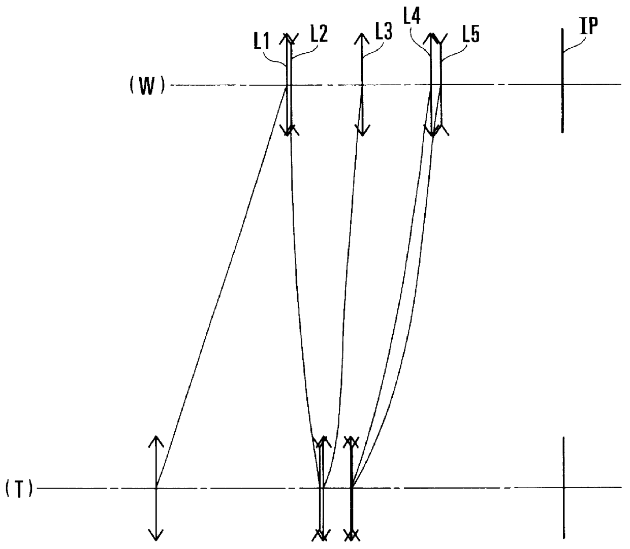
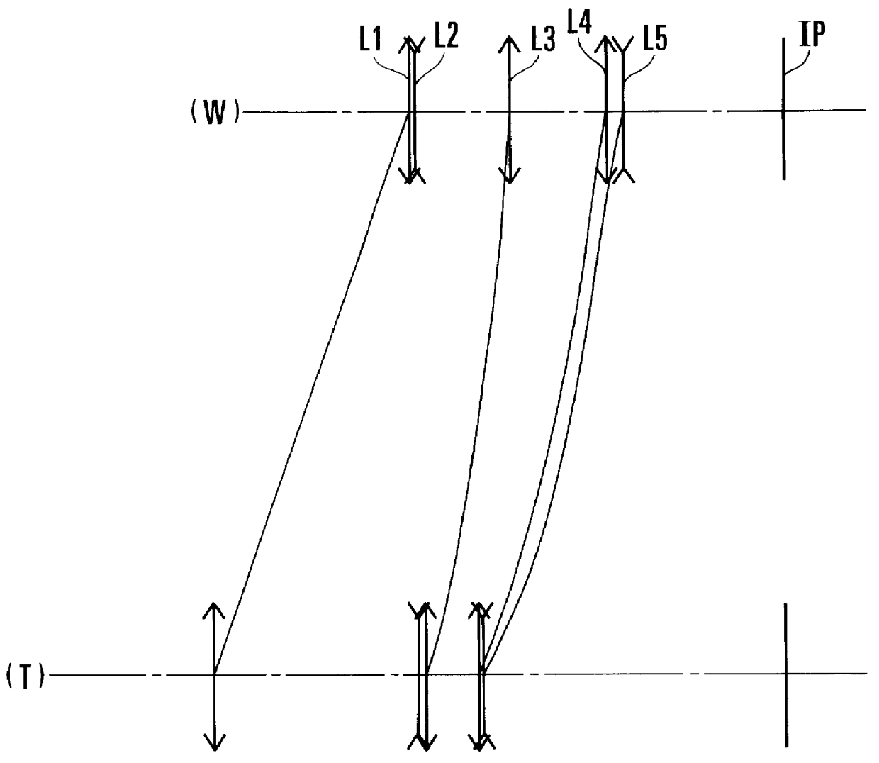
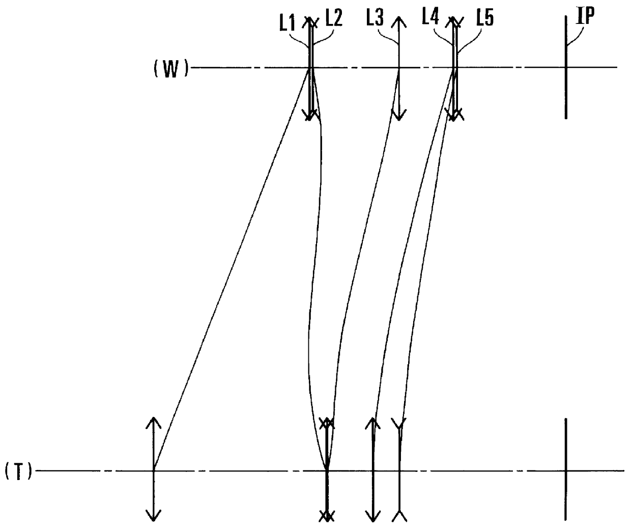
It will be appreciated from the foregoing that, according to the invention, with the use of five lens units as a whole, the appropriate rules of design are set forth for the relation in which to move the lens units during zooming, the refractive powers of the lens units, the selection of one of the lens units to be used for focusing, and the construction and arrangement of the constituent lenses of the focusing lens unit, thus making it possible to achieve a zoom lens with the field angle for the wide-angle end being 60 to 75 degrees or thereabout and the range being 6 to 9 or thereabout, while still maintaining a good stability of high optical performance throughout the entire zooming range and throughout the entire focusing range.


PUM


Abstract

A zoom lens includes, in order from an object side to an image side, a first lens unit of positive refractive power, a second lens unit of negative refractive power, a third lens unit of positive refractive power, a fourth lens unit of positive refractive power and a fifth lens unit of negative refractive power, wherein, during zooming from a wide-angle end to a telephoto end, at least the first, third, fourth and fifth lens units are axially moved toward the object side in such a manner that a separation between the first lens unit and the second lens unit increases and a separation between the second lens unit and the third lens unit decreases, and wherein the fifth lens unit is axially moved toward the image side to effect focusing on from an infinitely distant object to a closest object.

Description

1. Field of the InventionThe present invention relates to zoom lenses and, more particularly, to high-range zoom lenses suited to photographic cameras, video cameras or electronic still cameras. Still more particularly, the invention relates to zoom lenses having a range of 6 to 9 with a field angle for the wide-angle end of 60 to 75 degrees and an F-number of 4 to 6, while still maintaining a good stability of optical performance throughout the entire zooming range and throughout the entire focusing range.2. Description of Related ArtFor the objective system of the photographic camera or video camera, there has been a demand that the zoom lens to be used is of high range with high contrast and high optical performance being maintained stable over the entire zooming and focusing ranges.In Japanese Laid-Open Patent Application No. Sho 63-195618, there has been proposed a zoom lens which comprises five lens units of positive, negative, positive, positive and negative refractive powers...

Claims


Application Information

Patent Timeline
Patent Type & Authority Patents(United States)
IPC IPC(8): G02B15/163G02B15/173G02B13/18G02B15/20
CPCG02B15/173G02B15/145113
Inventor NISHIO, AKIHIRO
Owner CANON KK
Why Eureka
Try Eureka