Driving device

Inactive Publication Date: 2001-04-10
MINOLTA CO LTD
View PDF14 Cites 72 Cited by
  • Summary
  • Abstract
  • Description
  • Claims
  • Application Information

AI Technical Summary

Benefits of technology

In this driving device, the surface of the graduated member is given variations of a predetermined property that can be used as graduations. One graduated member is shared to detect the positions of all of the driven members. Accordingly, it is possible to minimize the space required to arrange the graduated member. In addition, since no deviation occurs between the graduations read by the individual sensors, it is possible to keep all of the driven members in a desired positional relationship accurately.
The graduated member may be designed to serve also as a restricting member for restricting the movement of the driven members in a direction perpendicular to the driving direction. This arrangement eliminates the need to provide a restricting member separately and thus helps further reduce the space required.
The graduated member may have only one surface having the property. If this surface is flat, all of the sensors need to be arranged so as to face the graduated member from the same direction. If the graduated member is cylindrical and has a curved surface, the individual sensors can be arranged so as to face the graduated member from different directions, and thus the sensors and the driven member

Problems solved by technology

This means that the driving rods are unnecessarily long, occupying unduly large spaces.
When piezoelectric actuators are used as driving elements, even though the driving rods are made of a highly rigid material, it is impossible to eliminate elastic deformation completely.
For this reason, the longer the driving rods, the more difficult it is to drive the driven members efficiently because of absorption of the driving force from the piezoelectric actuators and delay in transmission of the driving force.
Moreover, this leads to loss of energy.
Furthermore, the longer the driving rods, the more rigid they need to be.
This narrows the choice of the material of the driving rods and increases their cost.
However, in a driving device of this type, the expansion and contraction of one piezoelectric actuators are transmitted, as vibration, to the other piezoelectric actuator through the base block, and this may adversely affect driving.
For example, such vibration causes variations in

Method used


Image

  • Driving device
  • Driving device
  • Driving device

Examples


first embodiment

Hereinafter, driving devices embodying the present invention, as applied to driving of the taking lens of a camera, will be described with reference to the accompanying drawings. The driving device of a first embodiment is for driving a zoom lens system composed of four lenses as shown in FIG. 9. In this zoom lens system, the first and third lenses, L1 and L3 are fixed, and the second and fourth lenses L2 and L4 are movable. The relationship between the focal length and the positions of the individual lenses is shown in FIG. 10. The lenses L2 and L4 are movable through several millimeters.

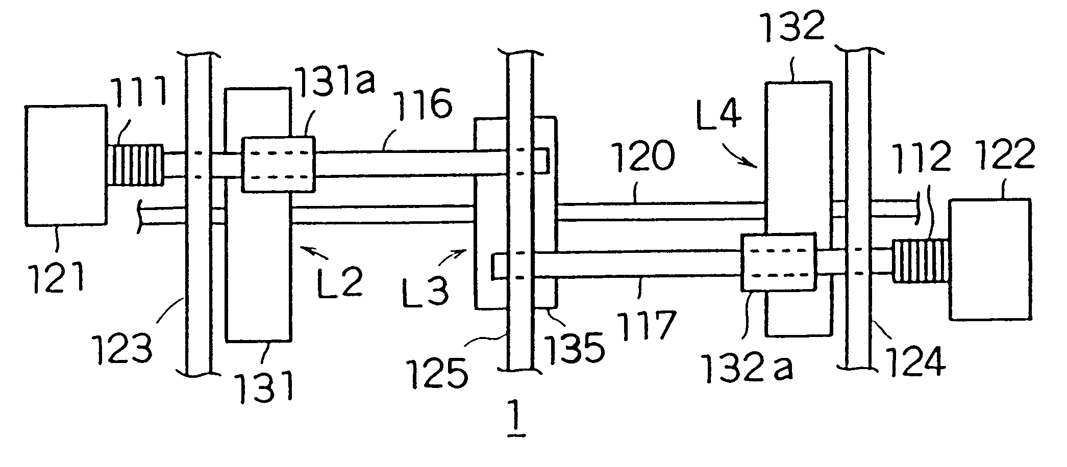
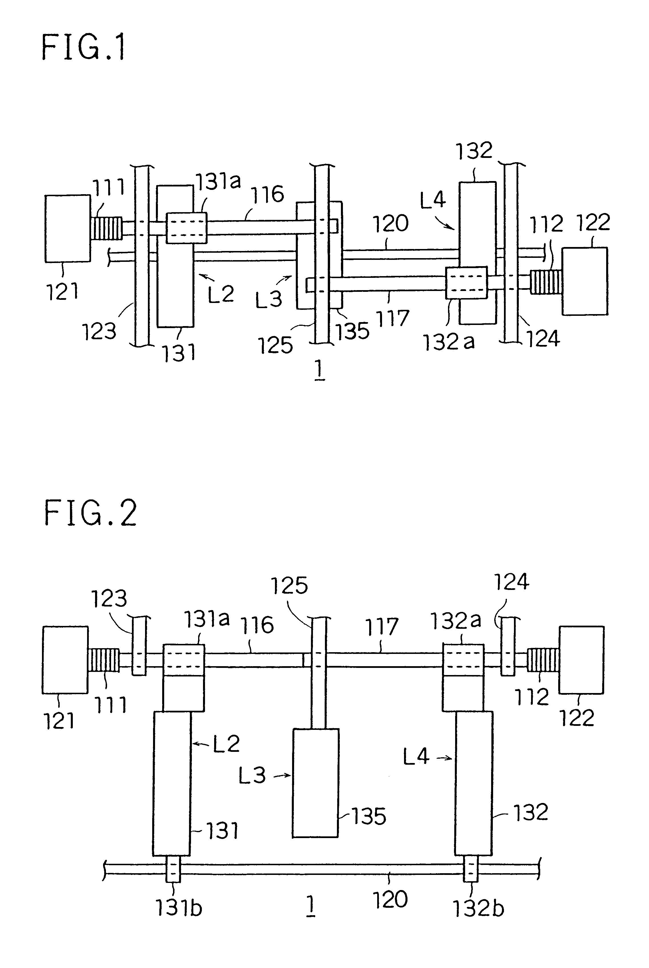
A plan view and side view of the driving device 1 of the first embodiment, for driving the second and fourth lenses L2 and L4, are shown in FIGS. 1 and 2, respectively. Note that the first lens L1 is not shown in these figures. The driving device 1 is provided with two piezoelectric actuators 111 and 112 serving as driving elements, two driving rods 116 and 117, one guide rod 120, two base blocks 1...

second embodiment

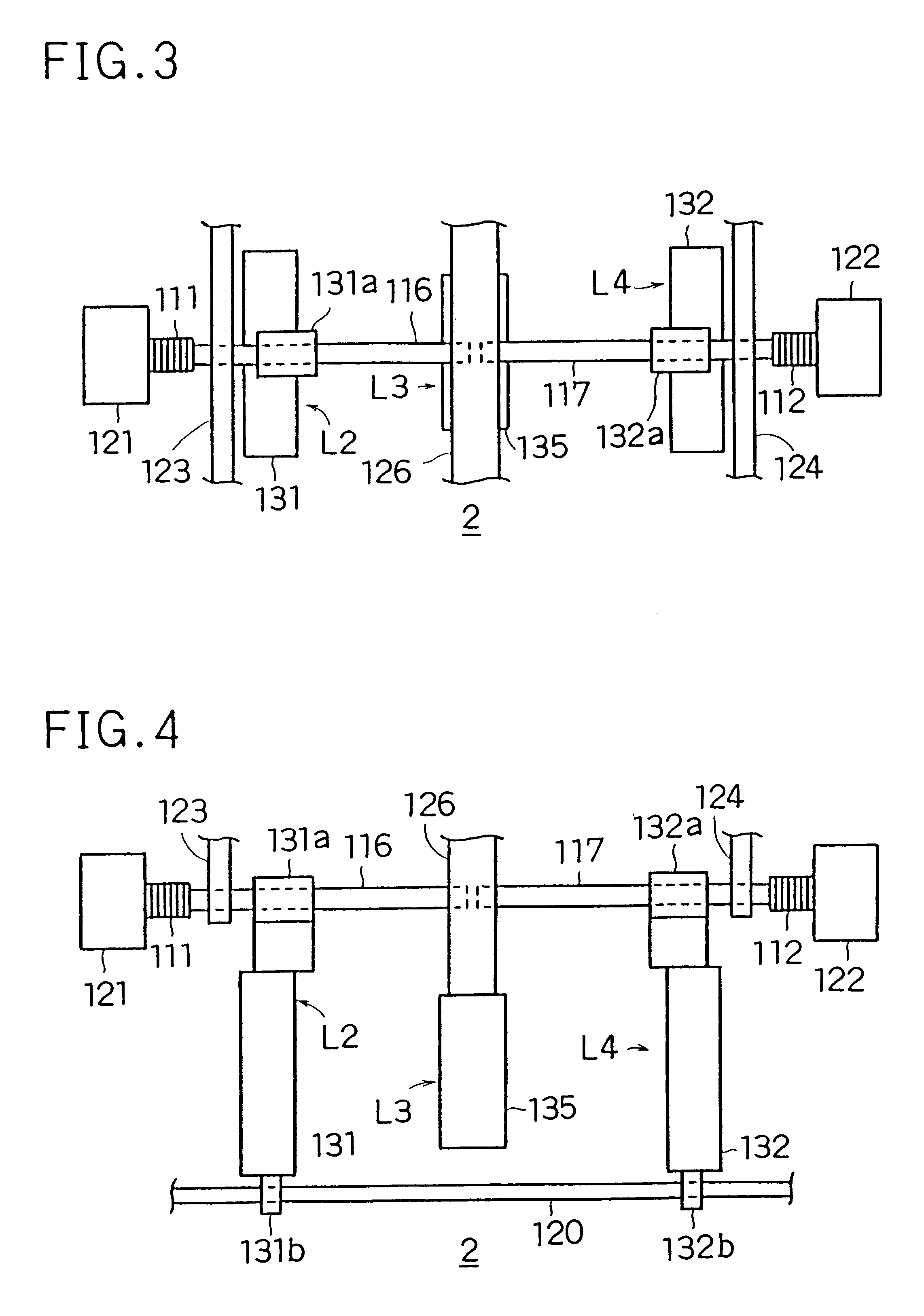
A plan view and a side view of the driving device 2 of a second embodiment are shown in FIGS. 3 and 4, respectively. This driving device 2 is also for driving the second and fourth lenses L2 and L4 of the zoom lens system shown in FIG. 9. However, this driving device 2 is different from the driving device 1 in that, in this driving device 2, the first and second driving rods 116 and 117 are arranged on the same line. The supporting wall 126 for supporting the tip-end portion of the driving rods 116 and 117 is made thicker than the previously described supporting wall 125, and has only one through hole that is shared to support the tip-end portion of the driving rods 116 and 117. The tip end of the driving rod 116 and the tip end of the driving rod 117 are placed several hundred micrometers or more apart from each other, so that they do not come into contact with each other.

By arranging the driving rods 116 and 117 on the same line in this way, it is possible to make the space occupi...

third embodiment

The driving device of a third embodiment is for driving a zoom lens systems composed of three lenses as shown in FIG. 11. The first, second, and third lenses L1a, L2a, and L3a are all movable. The relationship between the focal length and the positions of the individual lenses is shown in FIG. 12.

A plan view and a side view of the driving device 3 of the third embodiment are shown in FIGS. 5 and 6, respectively. This driving device 3 provided with, in addition to the piezoelectric actuators 111 and 112 and the driving rods 116 and 117 arranged on the same line, another piezoelectric actuator 113 and another driving rod 118. The driving rod 118 is arranged parallel to the driving rod 116, and the piezoelectric actuator 113 is, together with the piezoelectric actuator 111 and the driving rod 116, the second lens L2a is driven by the piezoelectric actuators 113 and the driving rod 118, and the third lens L3a is driven by the piezoelectric actuators 112 and the driving rod 117.

The lens ...


PUM


Abstract

A plurality of movable lenses included in a zoom lens system are driven individually by piezoelectric actuators provided one for each lens. Two driving rods are arranged at different positions along the same line in such a way that neither of the driving rods reaches into the driving stroke of the lens driven by the other. Each driving rod has a piezoelectric actuator provided at its end farther from the other. Alternatively, a plurality of piezoelectric actuators are fixed to a single base block having a groove or a surface level difference to restrict propagation of vibration between the piezoelectric actuators. A graduated member having N-pole and S-pole regions formed alternatively thereon with a predetermined pitch is fixed, parallel to the driving rods, to the driving device itself. A magnetic resistance sensor is attached to each lens frame so as to face the graduated member. Based on the outputs of the sensors, the positions of the individual lenses are detected.

Description

This application is based on application Nos. H10-187070, H10,187071 and H10-192608 filed in Japan, the content of which is hereby incorporated by reference.BACKGROUND OF THE INVENTION1. Field of the InventionThe present invention relates to a driving device for driving a plurality of driven members in the same direction or in opposite directions, and particularly to a driving device having a driving element and a driving rod provided for each of driven members so that the driven members can be driven individually.2. Description of the Prior ArtTo drive a plurality of driven members along the same line while keeping them in a predetermined positional relationship, it is customary to drive all of the driven members by means of a single driving element combined with a guide mechanism that guides the driven members along the driving direction while controlling their relative positions. For example, in a zoom lens system, helicoids having different pitches are provided, as a guide mecha...

Claims


Application Information

Patent Timeline
IPC IPC(8): G02B7/10
CPCG02B7/10
Inventor KUWANA, MINORUNISHIHARA, YASUO
Owner MINOLTA CO LTD
Why Eureka
Try Eureka