
Self-zooming camera

a self-zooming and camera technology, applied in the field of self-zooming cameras, can solve the problems of no simple button-free or hand-free method to effectively operate the zoom lens

Inactive Publication Date: 2010-11-25
DAVIES JOHN ANDREW
View PDF3 Cites 70 Cited by
  • Summary
  • Abstract
  • Description
  • Claims
  • Application Information

AI Technical Summary

Benefits of technology

[0006]The proximity sensors may be calibrated to approximate operators' eye-view through the framing of the camera's LCD display or it may be ‘sensitized’ to user preferences to allow full zoom control simply by moving the camera toward and away from the face through either the full range of camera zoom or through a preset range. With the use of motion detectors, the system could zoom a pre-selected amount by simple detection of forward motion, and, likewise, zoom out if backward motion is detected—this approach would provide an adequate back up to the self-zooming proximity detectors in low or difficult lighting situations.

Problems solved by technology

In the market, there exist many cameras, mobile devices which include cameras and video cameras that utilize some or all of the above mention items (optical zooms, digital zooms, motion sensors and proximity sensors), but none offer a simple button-free or hand-free method to effectively operate the zoom lens.

Method used


Image

  • Self-zooming camera
  • Self-zooming camera
  • Self-zooming camera

Examples


Embodiment Construction

[0018]The System.

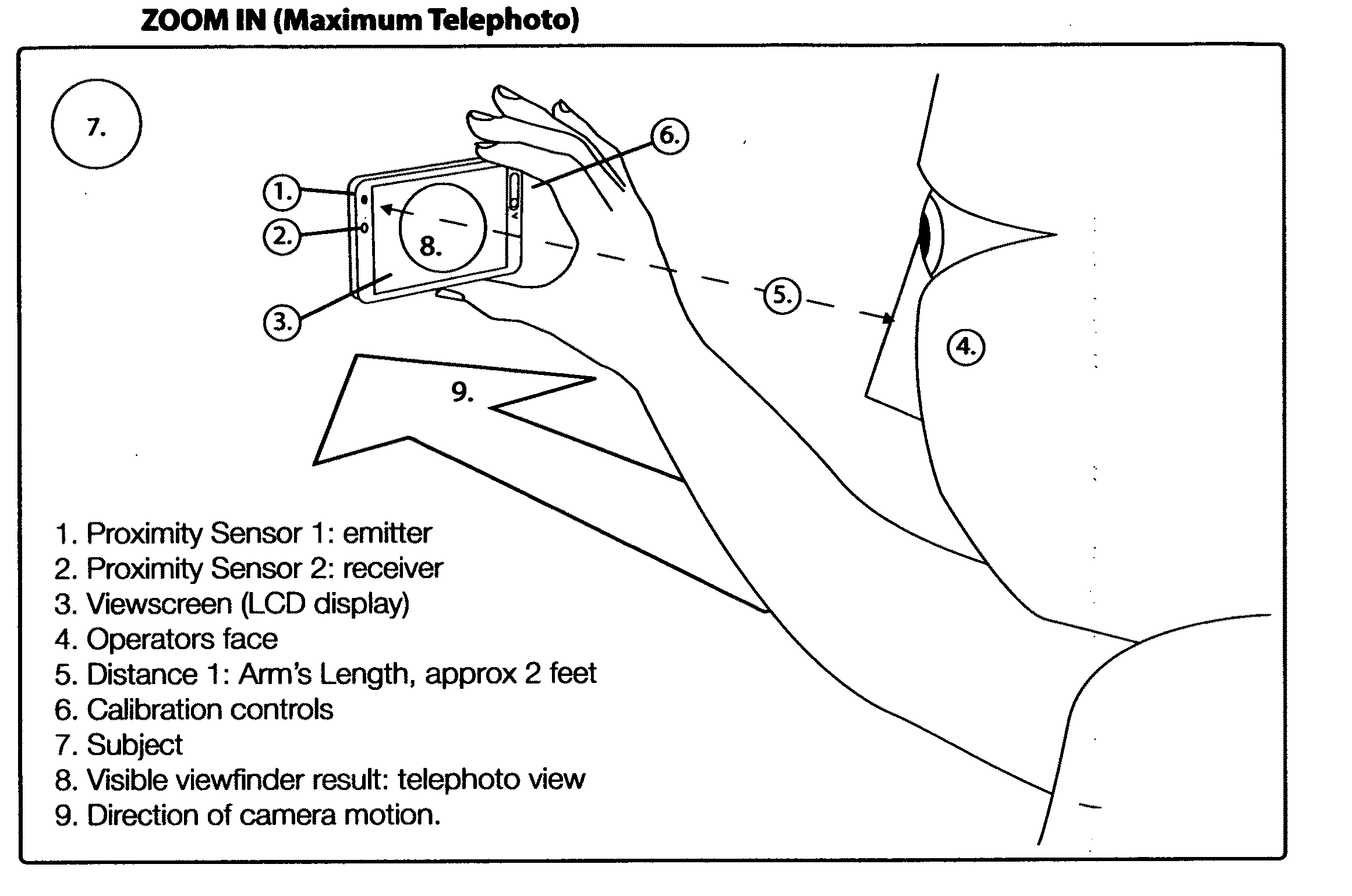
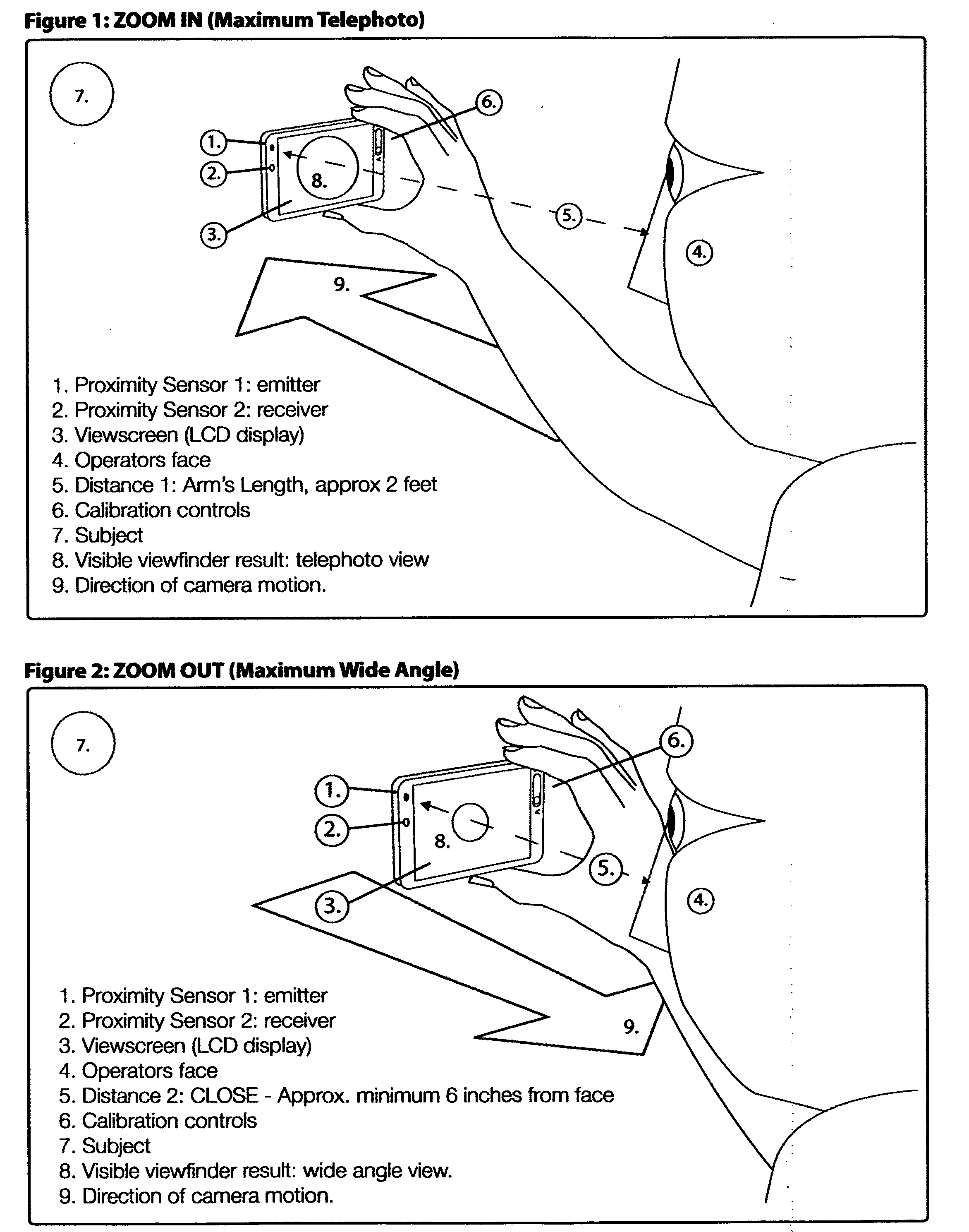
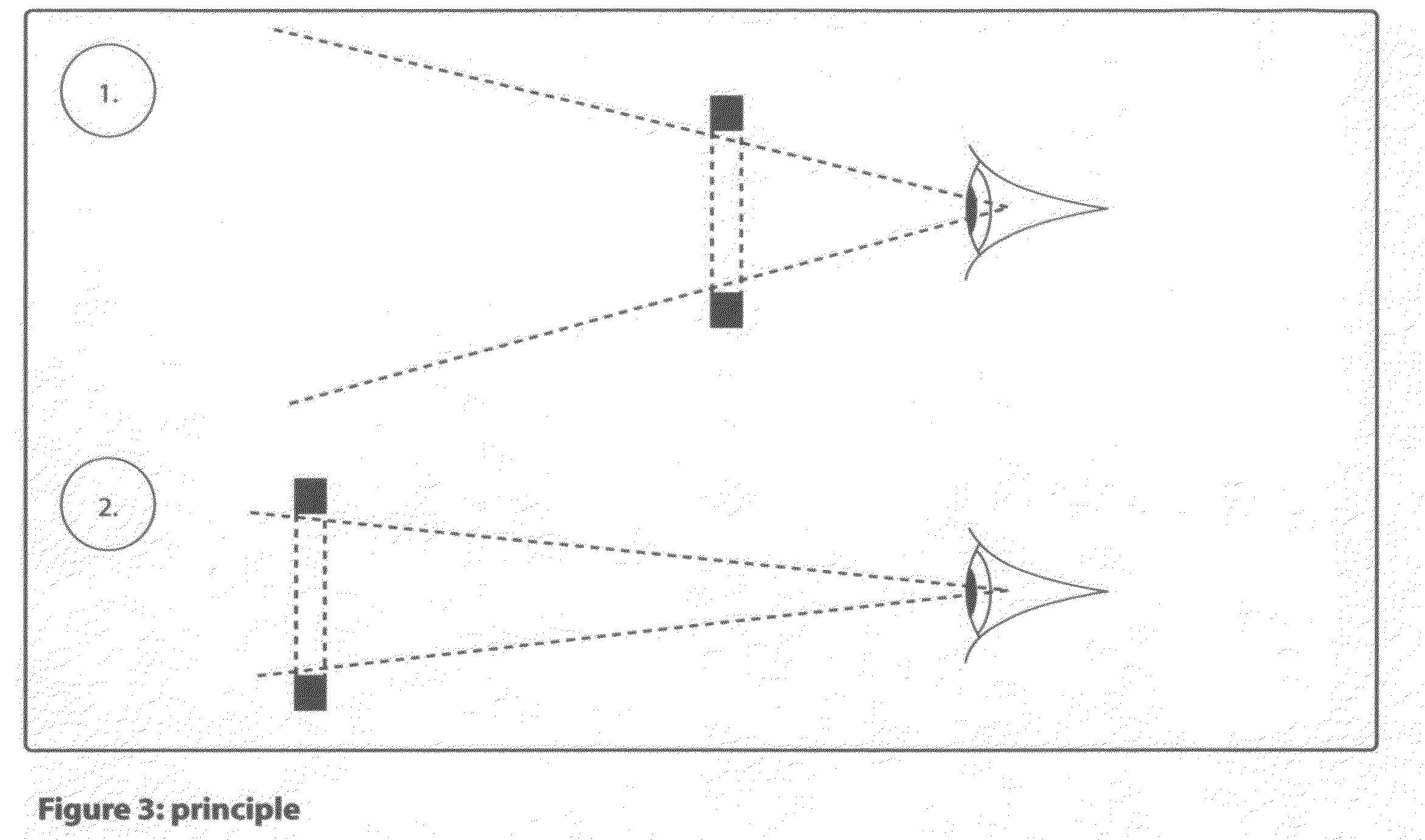
[0019]The Self-Zooming Camera utilizes proximity detectors and / or motion detectors in the camera or recording device to detect the position of the camera / recording device relative to the operator's eye or face—the further away from the operator's face; the more the camera lens is zoomed in (narrowing angle of view); the closer the camera is to the operator's face, the wider the angle of view from the lens. This approach to control is based upon the concept of approximating what the human eye sees when looking through a frame or viewfinder.

[0020]The camera or mobile device require the use of Infrared proximity detection (diffuse reflective sensing) to send light from camera to operator's face, and measure time on return to camera. It may also be possible using more accurate ultrasonic sensors, but the short range and limited application mean that the simplest measurement sensors should suffice. The maximum / minimum operating distance for the camera is a ‘comfortable’ ...


PUM


Abstract

The Self-Zooming Camera uses proximity detectors and / or motion detectors in the camera to detect the position of the camera / recording device relative to the operator's eye or face. At closest viewable distance to the face (approx. 6 inches), the zoom lens operates at it's widest angle or user-specified widest angle setting. At furthest extent from the face (arm's length, approximately 2 feet), the camera zooms to its longest telephoto extent or user-specified longest zoom setting.The Self-Zooming Camera allows simple and creative zoom operation of a camera, video recorder or mobile device with camera without using buttons or zoom / focus pulling—replacing traditional controls with intuitive gesture or camera motion.

Description

FIELD OF THE INVENTION[0001]Digital Photography, commercial photography, consumer electronics, videography.BACKGROUND OF THE INVENTION[0002]Digital photography and photography in general has made many advances in recent years. With the development and incorporation of proximity sensors, motion sensors, touch screens and various other techniques, all with the aim of making the the camera itself is becoming more and more intuitive and user-friendly.[0003]Many cameras now feature automation of some kind, whether exposure, color balance, flash, film speed setting or similar. Zoom lenses can now also be controlled in a much simpler manner, particularly on compact or ‘point-and-shoot’ cameras and mobile devices, replacing traditional zoom rings (mechanical lens rings similar to focus rings which when turned, rearrange lens elements to alter the users' field of view) with simple sliders (touch screen or button-based) where the user pushes to the left or right or up and down to achieve zoom...

Claims


Application Information

Patent Timeline
Patent Type & Authority Applications(United States)
IPC IPC(8): G03B17/00
CPCG03B17/00
Inventor DAVIES, JOHN ANDREW
Owner DAVIES JOHN ANDREW
Learn More