

Anchor for cables
a technology for anchoring cables and cables, applied in the direction of traction harnesses, traffic signals, roads, etc., can solve the problems of small risk of serious vehicle damage and occupant injuries
- Summary
- Abstract
- Description
- Claims
- Application Information
AI Technical Summary
Problems solved by technology
Method used
Image

Examples
second embodiment
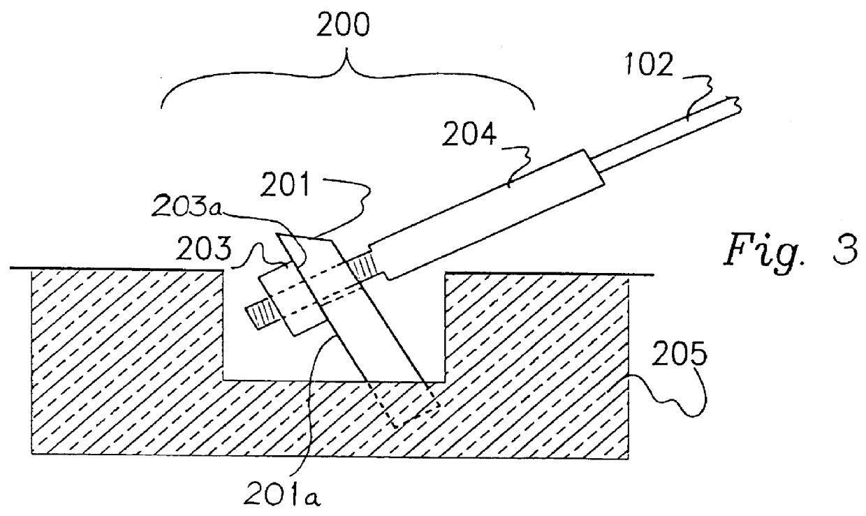
A variation of the embodiment shown in FIG. 3 can be seen in FIGS. 5 and 6. This variation incorporates an intermediate member 207 and a bearing member 208 between the anchor body 201 and the fastener 203. (The intermediate member 207 may be provided alone, without any other bearing member, or it may be in the form of a surface layer on the bearing member 208.) The bearing member 208 is preferably a metal plate.
Preferably the intermediate member 207 provides a means of consistent release, enabling the cable 102 to become dislodged from the anchor body 201 after a predetermined amount of deflection is applied to the cable. Preferably the intermediate member 207 is non-metallic. Preferably this member is resistant to corrosion or any major change over time in its frictional characteristics. Preferably this member is a rectangular plate or polymer such as nylon, high density polyethylene (HDPE) polytetrafluoroethylene (e.g. "Teflon" [registered trade mark]). Preferably the dimensions o...
third embodiment
A further version of the above-described embodiments is shown in FIGS. 7 to 10, in which the swaged fitting 204 is replaced by a mechanical fitting 250 attached to the end portion of a cable 102 which extends through a slot 206 in the anchor body 201. In this embodiment the front end of the fitting 250 abuts against the rear surface of the anchor body 201 with the optional interposition of an intermediate member 207 as described above. The anchor body 201 is welded to a base plate 251 having bolt 252 allowing it to be fixed to the road surface.
The fitting 250 (FIG. 10) comprises a cylindrical barrel 253 with a bore having a tapering inner surface 254, into which the cable is inserted from the narrower end. A set of wedges 255 are inserted from the opposite end of the barrel 253, between the inner surface 254 and the cable (not shown in FIG. 10). A cap 256 screwed into the barrel 253 compresses a coil spring 257 which prevents accidental release of the wedges 255, while tension in th...
fourth embodiment
FIG. 11 shows an alternative form of anchoring device, which comprises an anchor body 105 which is set in a concrete foundation 104, below ground level. A threaded fitting 103 is swaged to the cable 102 and attached to the anchor body 105 through an aperture in the anchor body 105. The anchor body 105 is a substantially rectangular structure angled and set in the concrete foundation 104. The threaded fitting 103 is held within the anchor body 105 by one or more fasteners 109 on the inner side of the body 105.
The fitting 103 at its upper end comprises an unthreaded metal collar 108 which has a neck 106 that is substantially narrower than the collar part.
The fitting 103 is made of steel having suitable flow characteristics for the swaging process and high tensile strength combined with a section adapted to fracture at a predetermined position when subjected to a shearing force. High tensile strength is required to ensure the threaded fitting can withstand the high tensile load to whic...
PUM
 Abstract
Description
Claims
Application Information