Holder for cylindrical cell in conveyor system

a technology of conveying holder and cylindrical cell, which is applied in the direction of cell components, charge manipulation, furnaces, etc., can solve the problems of hardly achieving the required properties of cells, changing the position and posture of cells relative to the position of the conveying holder, and difficult to convey cells

Inactive Publication Date: 2000-05-30
PANASONIC CORP
View PDF13 Cites 80 Cited by
  • Summary
  • Abstract
  • Description
  • Claims
  • Application Information

AI Technical Summary

Problems solved by technology

It is, however, difficult for the cell conveying holder shown in FIG. 6 to have a true roundness of the cell holding space defined by the inner walls of the two holder shells 1a and 1b.
As it is impossible to stably support the cell, it is hardly attained to produce cells of required properties effectively.
This, together with the fact that the cells cannot be stably supported, may cause changes in the positions and posture of cells relative to the conveying holder, while the conveying holders supporting the cell in its upright state are slid with or collided against each other on a transfer conveyor in the manufacturing process or on a turn table for temporal storage of unfinished products.
Also, due to the projection and the gap, the conveying holder itself may stick or stall in a feeder shoot or between the guides.

Method used


Image

  • Holder for cylindrical cell in conveyor system
  • Holder for cylindrical cell in conveyor system
  • Holder for cylindrical cell in conveyor system

Examples


Embodiment Construction

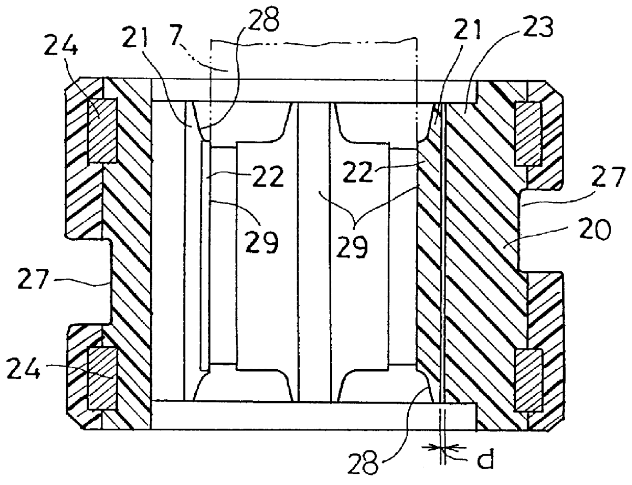
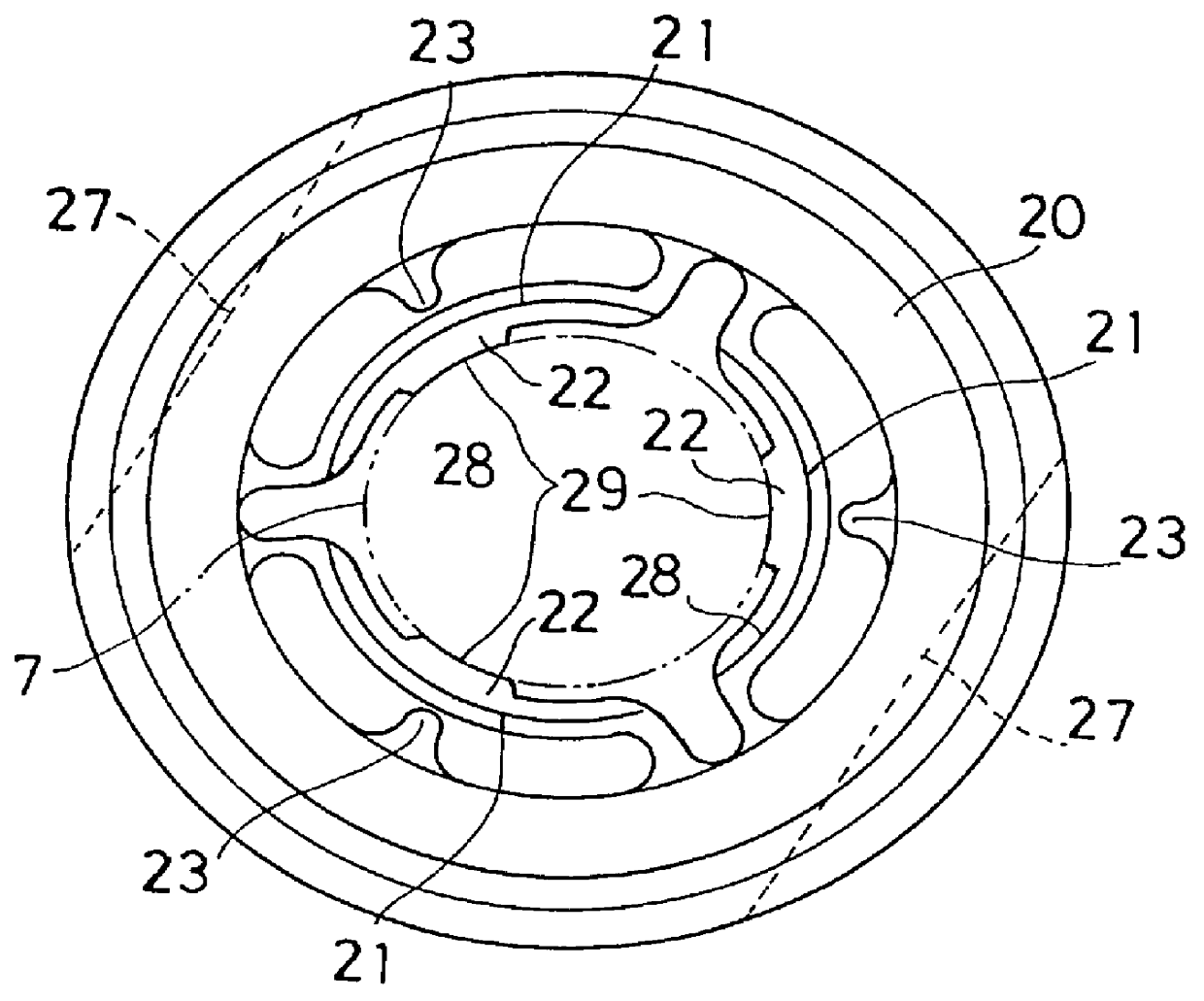
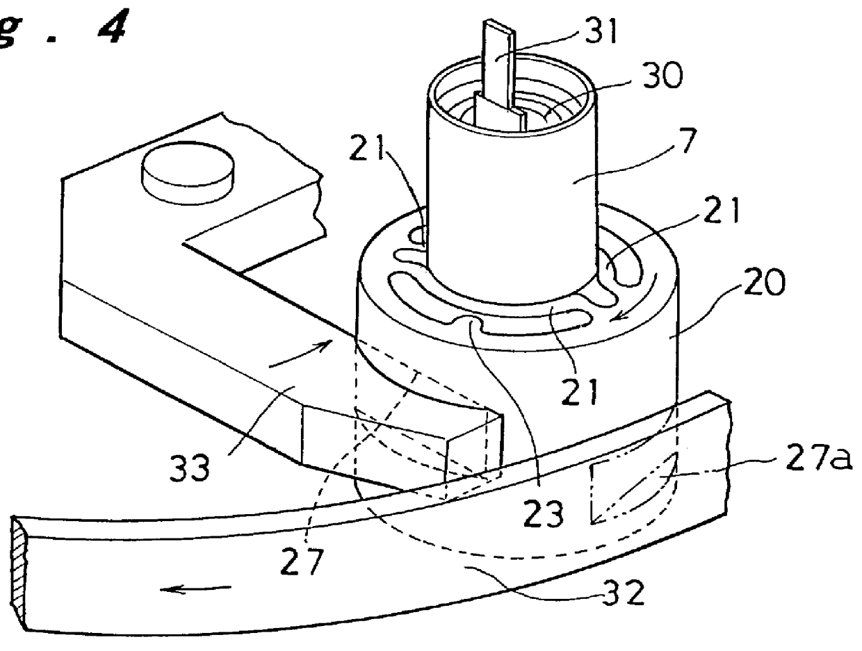
Preferred embodiments of the present invention will be described in more detail referring to the accompanying drawings. FIGS. 1 to 3 illustrate a conveying holder for holding a cylindrical cell according to one embodiment of the present invention. FIG. 1 is a plan view, FIG. 2 is a longitudinal cross sectional view, and FIG. 3 is a cut-off perspective view. As shown, the conveying holder or holder assembly comprises an outer wall member 20 of cylindrical shape, three inner wall elastic portions 21 of arcuate shape in cross section spaced at a certain distance from the inner side of the outer wall member 20 and disposed along a circle being concentric with the outer wall member 20, three cell holding portions 22, each projecting inwardly from a center of the inner side of the inner wall elastic portion 21, and three deformation limiting bosses 23, each projecting inwardly from the inner side of the outer wall member 20 towards the corresponding cell holding portion 22, which are all ...


PUM

PropertyMeasurementUnit
frictional coefficientsaaaaaaaaaa
thicknessaaaaaaaaaa

Abstract

A conveying holder for cylindrical cell is provided which is capable of stably supporting a cylindrical cell irrespective of variation in outer diameter of the cell or impact during transfer. An outer wall member 20 of which inner diameter is greater than the diameter of a cylindrical cell 7 is provided. A plurality of elastic inner wall portions 21 are concentrically arranged to have a distance from the inner side of the outer wall member 20, each elastic inner wall portion joined at both ends to the outer wall member 20. A cell holding portion 22 is provided projecting inwardly from the inner side of each elastic inner wall portion 21 and having a cell holding surface 29 thereof corresponding in shape to the outer side of the cylindrical cell 7. The cell holding surfaces 29 are arranged along a concentric circle which is smaller in diameter than the cylindrical cell 7 so that they can hold the cylindrical cell 7 in-between under pressure.

Description

1. Technical Field of the InventionThe present invention relates to a conveying holder for a cylindrical cell being manufactured in an assembling process, which determines the orientation of the cell and conveys the cell while supporting it in an upright state.2. Description of Related ArtsAs the demand for batteries is now increasing sharply, it is desired to produce a great amount of batteries while maintaining their quality level as well as reliability. In a process of manufacturing batteries, unfinished batteries are carried by a known conveyor system from one step to another for filling a cell housing with an electrode assembly, pouring an electrolyte, applying a sealer, closing the cell housing with a sealing member, and so on. In the above mentioned processes, cell housings are held in their upright state by a conveying holder for a series of the steps. Such a conveying holder may be used to hold a cell housing, an in-process cell, or a finished cell product at each step for ...

Claims


Application Information

Patent Timeline
Patent Type & Authority Patents(United States)
IPC IPC(8): B65G17/32H01M2/10B25J15/08H01M50/202H01M50/227
CPCB65G17/32H01M2/10B65G2201/0261B65G2201/02Y02E60/10H01M50/202H01M50/227
Inventor KUMAKIRI, HIDEYUKIMIYAHISA, MASAHARUTANIMURA, HARUONAKATSUKA, SABURO
Owner PANASONIC CORP
Why Eureka
Try Eureka