Eccentric spacer for an in-line skate

a technology of in-line skates and spacers, which is applied in the field of skates, can solve the problems of extreme load on skaters, loose h-blocks, and gap between the sole of the boot and the frame, and achieve the effects of small area, large wheel spacing variation, and large wheel spacing variation

a technology of in-line skates and spacers, which is applied in the field of skates, can solve the problems of extreme load on skaters, loose h-blocks, and gap between the sole of the boot and the frame, and achieve the effects of small area, large wheel spacing variation, and large wheel spacing variation

US6070887AInactive Publication Date: 2000-06-06BENETTON SPORTSYST USA

Image

  • Eccentric spacer for an in-line skate
  • Eccentric spacer for an in-line skate
  • Eccentric spacer for an in-line skate

Examples


Embodiment Construction

Reference will now be made in detail to exemplary embodiments of the present invention which are illustrated in the accompanying drawings. Wherever possible, the same reference numbers will be used throughout the drawings to refer to the same or like parts.

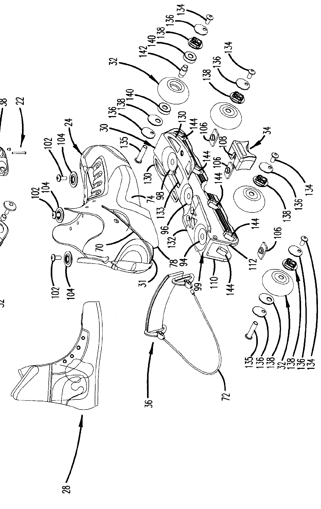
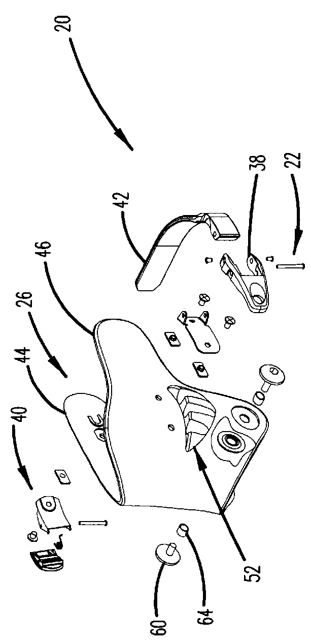
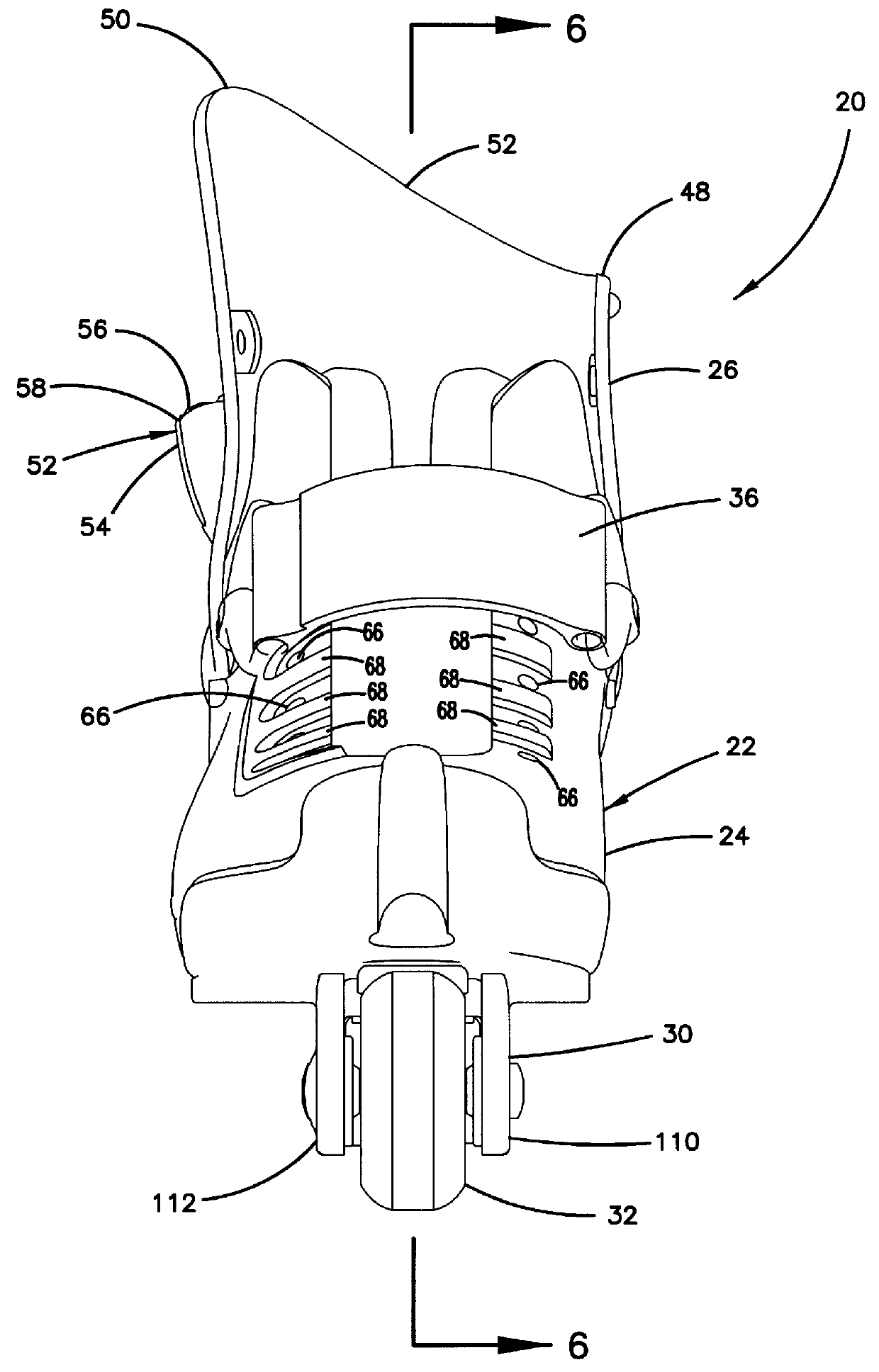
FIG. 1 shows an exploded view of an exemplary in-line skate 20 constructed in accordance with the principles of the present invention. The illustrated skate 20 is a right skate which is used in combination with a left skate constructed in the mirror-image of the right skate 20. Generally, the skate 20 includes a boot 22 having a shell portion 24, a cuff portion 26 and a removable inner liner 28. A low-profile frame 30 is connected to a sole 31 of the shell portion 24 of the boot 22. A plurality of wheels 32 are mounted in tandem along the length of the frame 30. An H-block 34 is positioned between the wheels 32 and is connected to a mid-region of the frame 30. The skate 20 is also equipped with an optional power strap 36 for tight...


PUM


Abstract

A diamond-shaped eccentric spacer suitable for use with an in-line roller skate. The spacer defines an eccentric first axle opening sized and shaped for receiving an in-line skate axle. The diamond-shaped spacer also includes a first corner positioned opposite from a second corner, and a third corner positioned opposite from a fourth corner. The eccentric first axle opening is aligned along a diagonal line that extends generally between the first and second corners.

Description

TECHNICAL FIELDThe present invention relates generally to the field of skates. More particularly, the present invention relates to roller skates having tandemly mounted wheels and eccentric spacers for mounting the wheels.BACKGROUNDIn recent years, roller skating and in-line skating have become extremely popular. Many participants in these sports have developed an interest in what is known as "aggressive" or "extreme" skating. Such skating includes jumping, flipping, sliding across raised surfaces, sliding down rails, and other similar types of maneuvers.Skates generally have a frame and a boot coupled to the frame. The boots of many in-line skates include hard outer shells covering portions of a soft inner liner. Typically, the frame of a skate is made of plastic or metal and has a platform with an upper surface and a lower surface. The platform generally has a toe area and a heel area, with the heel area being vertically higher than the toe area. The boot has a sole and is positio...

Claims


Application Information

Patent Timeline
06 Jun 2000
Publication
US6070887A
IPC
A63C17/06; A63C17/04
CPC
A63C17/06; A63C17/226; A63C2201/02
Inventors
CORNELIUS, DIRK L.; MITTERSINKER, GREGOR