Part washer

a technology of washer and washer body, which is applied in the direction of cleaning process and apparatus, cleaning using liquids, chemistry apparatus and processes, etc., can solve the problems of requiring a relatively large amount of floor space, failure of the complete assembly in operation, and ineffective removal of all of the debris from the finished part by the fluid jet. to achieve the effect of sealing the housing

Inactive Publication Date: 2000-06-13
VALIANT CO LTD
View PDF10 Cites 14 Cited by
  • Summary
  • Abstract
  • Description
  • Claims
  • Application Information

AI Technical Summary

Benefits of technology

The parts to be washed are sequentially moved by a conveyor system to a position adjacent the lower chamber. A shuttle assembly movable between a retracted position and an extended position selectively engages the part adjacent the lower chamber and moves the p

Problems solved by technology

One disadvantage is that the fluid jets are not wholly effective in removing all of the debris from the finished part.
Furthermore, any debris which is not removed from the finished part can result in failure of the completed assembly in operation.
A st

Method used


Image

  • Part washer
  • Part washer
  • Part washer

Examples


Embodiment Construction

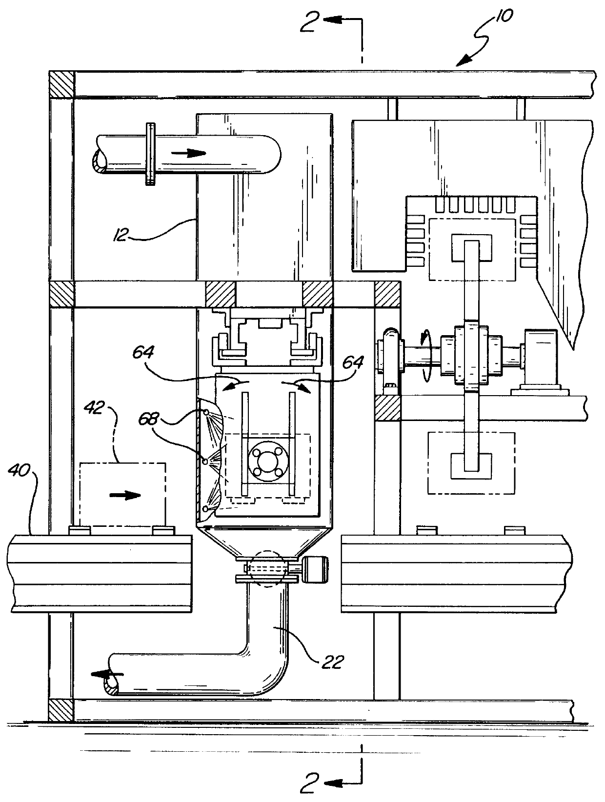
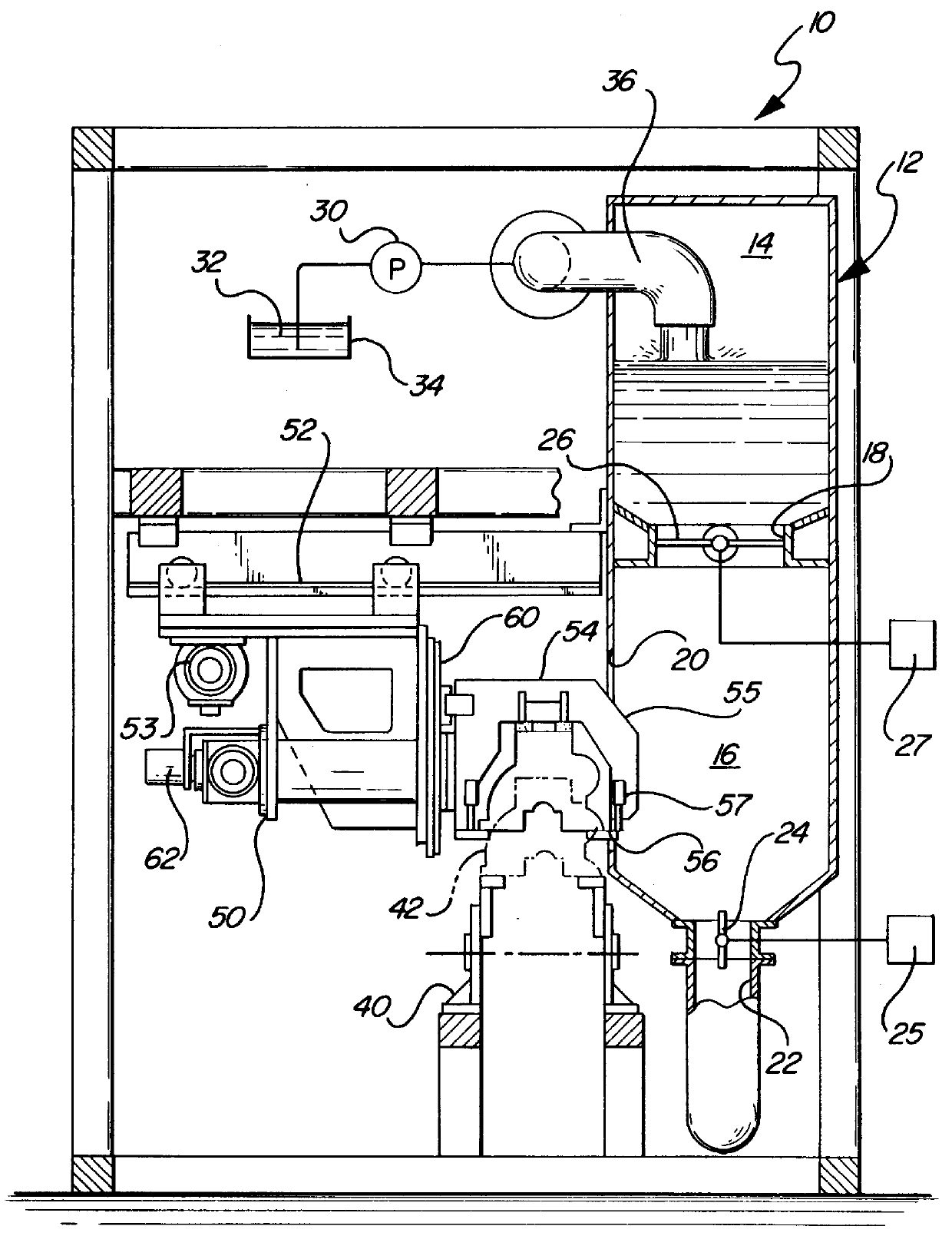
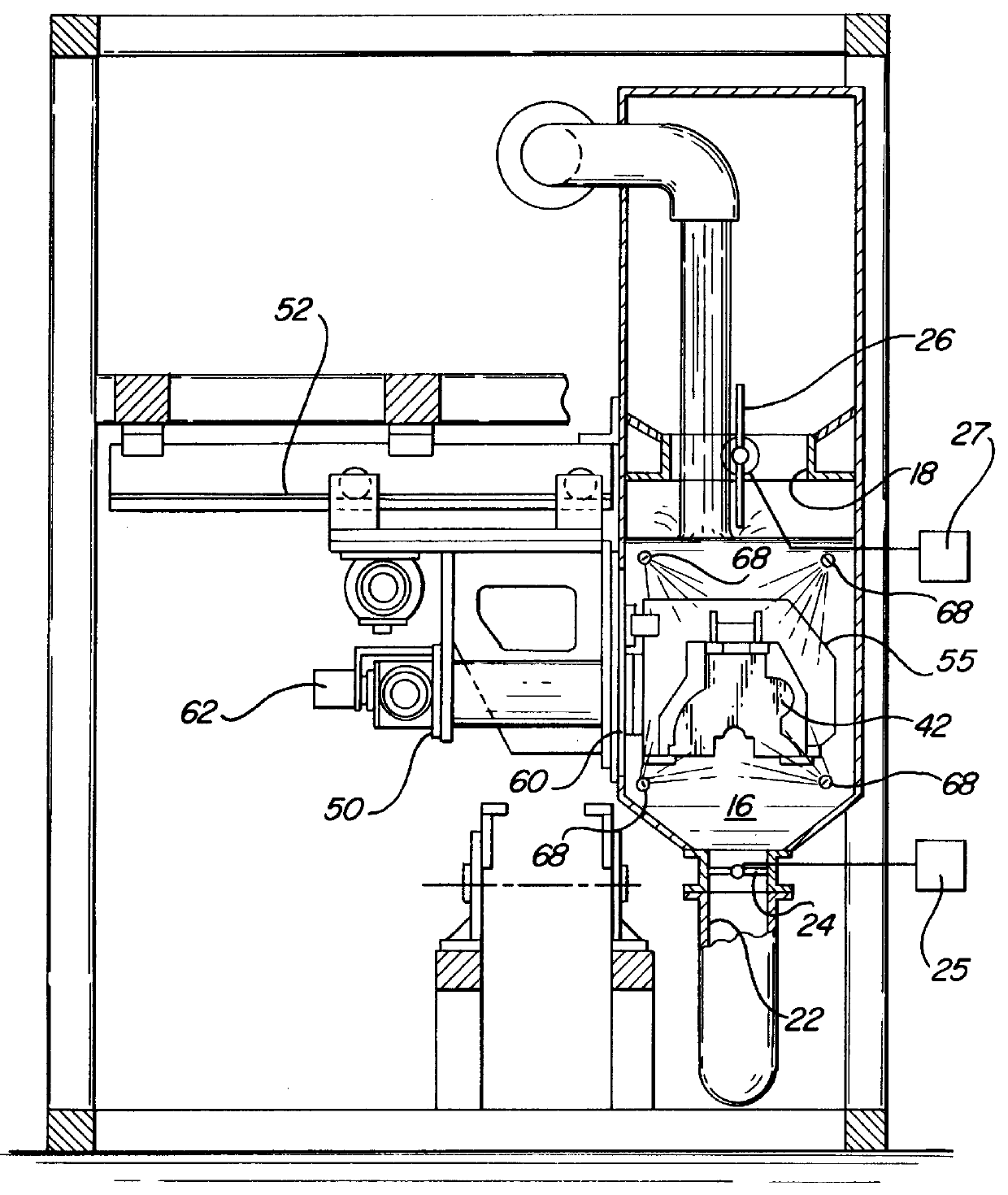
With reference first to FIGS. 1 and 2 of the patent drawing, a preferred embodiment of the part washer 10 of the present invention is there shown and comprises a washer housing 12 defining an upper chamber 14 and a lower chamber 16. As best shown in FIG. 2, a fluid passageway 18 fluidly connects the chambers 14 and 16 together. The washer housing 12 is preferably rectangular in cross-sectional shape and includes a side opening 20 open to the lower chamber 16 for a reason to be subsequently described.

With reference now particularly to FIGS. 2 and 3, a fluid drain 22 is open to the bottom of the lower chamber 16. A drain valve 24 is fluidly connected in series with the drain 22 and is movable between an open position, illustrated in FIG. 2, and a closed position, illustrated in FIG. 3. A drain valve control system 25 controls the actuation of the drain valve.

A flood valve 26 is fluidly connected in series with the passageway 18 and is movable between a closed position, illustrated in ...


PUM


Abstract

An industrial part washer is disclosed having a washer housing with an upper chamber, a lower chamber, and a fluid passageway connecting the chambers together. A fluid drain is connected to a lower chamber for draining fluid from it while a pump pumps a cleaning fluid into the upper chamber. A flood valve is positioned in the fluid passageway between the upper and lower chambers and this valve is movable between an open and a closed position. Parts are sequentially moved into a position adjacent the washer housing and are selectively loaded into the lower chamber, washed and, following completion of a wash cycle, subsequently unloaded from the lower chamber. A valve control closes the flood valve during the loading and unloading operations of the part into the lower chamber so that, during the loading and unloading portions of the wash cycle, the upper chamber at least partially and preferably completely fills with the cleaning fluid.

Description

I. Field of the InventionThe present invention relates to an industrial part washer.II. Description of the Prior ArtIn industrial manufacturing facilities, for example, the manufacture of automotive engine blocks or cylinder heads, it is necessary to thoroughly wash the completed part prior to final assembly. Such washing of the final part removes not only foundry sand and other debris as the result of casting operations, but also metal chips and debris entrapped within cavities, openings, etc. present in the part from machining operations.There has been many previously known part washers for washing such industrial parts. These previously known part washers typically comprise a washer housing having a conveyor which sequentially moves parts through the washing housing. Numerous spray jets are contained within the washing housing and have their outlets directed at the parts on the conveyor line. A pump pumps pressurized cleaning fluid, typically water, through the jets such that the...

Claims


Application Information

Patent Timeline
IPC IPC(8): B08B3/02
CPCB08B3/02
Inventor MCTAGGART, MICHAEL DOUGLAS
Owner VALIANT CO LTD
Why Eureka
Try Eureka