Thermostatic mixing valve

a technology of mixing valve and thermostatic valve, which is applied in the direction of temperatue control, process and machine control, instruments, etc., can solve the problems of large fluctuations in the temperature of the mix water, objectionable noise, inaccurate reaction of the thermal actuator,

Inactive Publication Date: 2000-06-27
ADEMCO INC
View PDF11 Cites 80 Cited by
  • Summary
  • Abstract
  • Description
  • Claims
  • Application Information

AI Technical Summary

Benefits of technology

When the temperature of fluid passing from the mixing chamber over the cup increases, the temperature-sensing device moves the fluid flow regulator downward to limit the flow of fluid from the first fluid chamber to the mixing chamber and increase the flow of fluid from the second fluid chamber to the mixing chamber, and when the temperature of fluid passing from the mixing chamber over the cup decreases, the temperature-sensing device moves the fluid flow regulator upward to limit the flow of fluid from the second fluid chamber to the mixing chamber and increase the flow of fluid from the first fluid chamber to the mixing chamber, thereby causing fluid flowing from the fluid outlet to remain close to a preset temperature which is set by the adjustment device.

Problems solved by technology

However, when steady state conditions are suddenly disturbed, such as, for example, when a nearby flushometer is being activated, large fluctuations in the mix water temperature can occur.
This can cause wide ranges of temperatures which are flowing across thermal actuator 14, which can result in inaccurate reactions of the thermal actuator 14.
Furthermore, the flow of water through the coils of bias spring 18 can cause the spring to vibrate, thereby creating a noise which is objectionable.

Method used


Image

  • Thermostatic mixing valve
  • Thermostatic mixing valve
  • Thermostatic mixing valve

Examples


Embodiment Construction

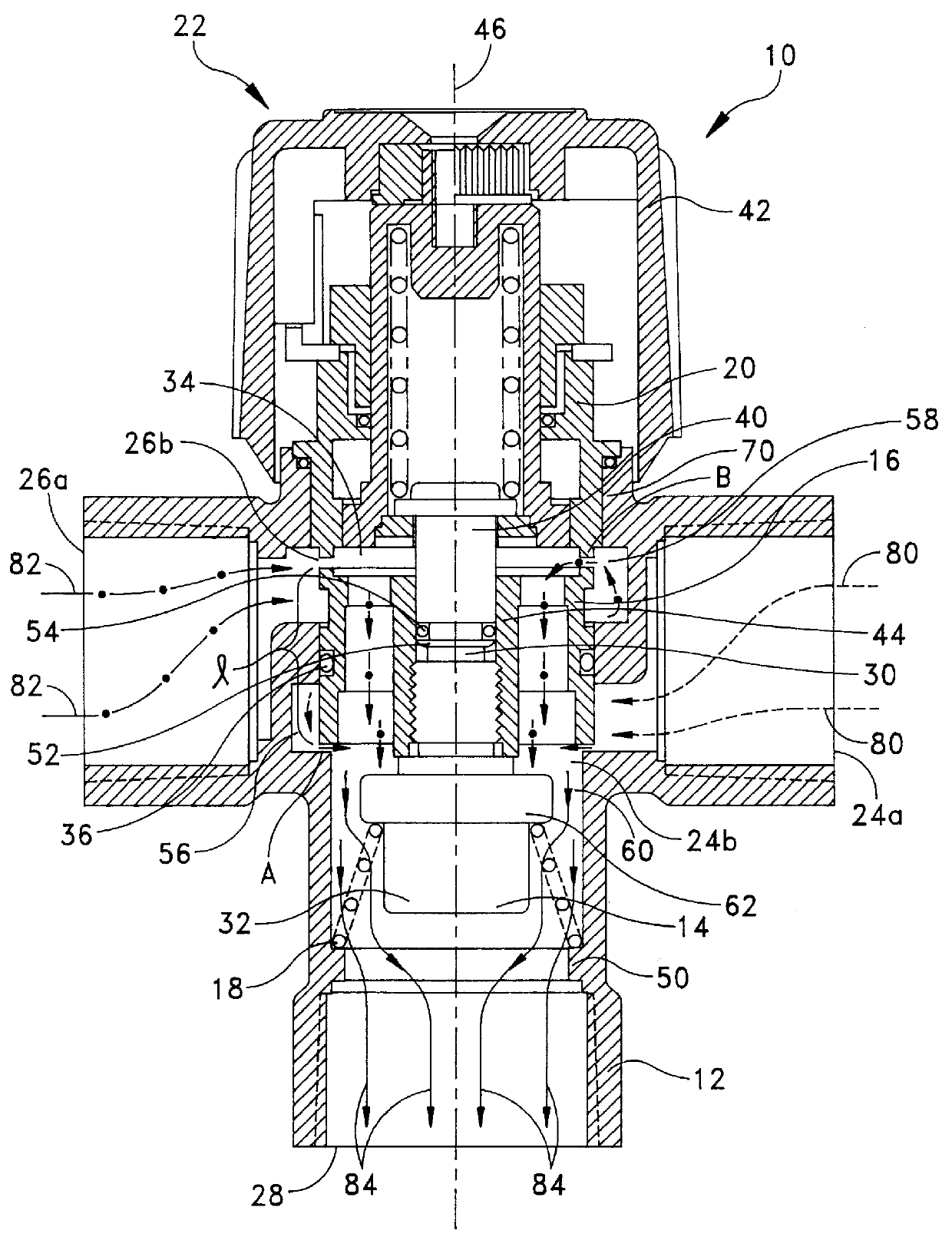
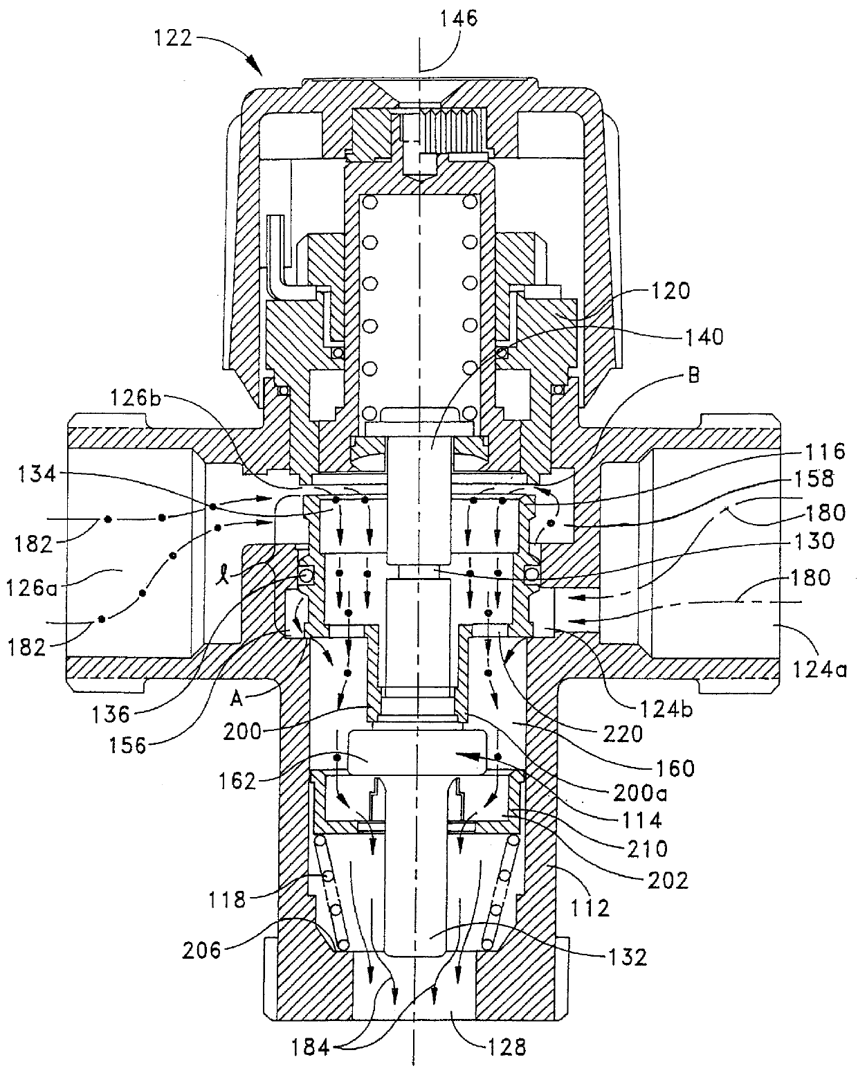
Referring now to FIGS. 2-6, an improved thermostatic mixing valve of the present invention will be described. As shown in FIG. 2, a mixing valve 100 includes a body 112, a thermal actuator 114, a spool 116, a biasing spring 118, a body cover 120 and a temperature selection device 122. The body 112 incorporates a hot port, made up of an external hot port 124a and an internal hot port 124b, a cold port, made up of an external cold port 126a and an internal cold port 126b, and a mix port 128. Body 112 also includes a hot annular groove 156 and a cold annular groove 158. The body 112 is typically formed from forged or cast metal.

The spool 116 is located between surface A of the body 112 and surface B of the body cover 120. Similar to the mixing valve 10 of FIG. 1, the distance between surface A of the body 112 and surface B of the body cover 120 is greater than the length l of spool 116. The difference in the distance between surface A of body 112 and surface B of body cover 120 and the...


PUM


Abstract

A mixing valve receives fluid from a first source and fluid from a second source and outputs a mixture of the fluids. The mixing valve includes a valve body including a first fluid inlet, a first fluid chamber, a second fluid inlet, a second fluid chamber, and a fluid outlet. The mixing valve further comprises a fluid flow regulator mounted within the housing, wherein a lower surface of the fluid flow regulator is disposed within the first fluid chamber and an upper surface of the fluid flow regulator is disposed within the second fluid chamber. The fluid flow regulator is mounted within the valve body in such a way as to permit movement of the fluid flow regulator along a longitudinal axis of the valve body. The fluid flow regulator includes a central hub which extends below the lower surface into the mixing chambr. A temperature-sensing device is mounted to the central hub of the fluid flow regulator and is constructed and arranged for sensing a temperature of fluid which flows from the mixing chamber to the outlet.

Description

1. Field of the InventionThe present invention generally relates to mixing valves, and more particularly to a thermostatic mixing valve having an improved mixing chamber and a diffuser for facilitating the mixing of a hot fluid and a cold fluid.2. Discussion of the Related ArtThermostatic mixing valves are commonly used in plumbing systems. They typically take hot water from a water heater and cold water as supplied to the building by the water company and blend the hot and cold water to a desired intermediate temperature. The blended (or mixed) water is then fed into the hot water supply piping of the building. For a number of reasons it is generally desirable to have the hot water generator produce water hotter than that desired at the plumbing fixture, thus the need for a mixing valve. The valves are so constructed that the temperature of the mixed water remains constant, or nearly constant, regardless of the actual hot and cold water temperatures and regardless of the flow rate....

Claims


Application Information

Patent Timeline
Patent Type & Authority Patents(United States)
IPC IPC(8): G05D23/13G05D23/01
CPCG05D23/1346
Inventor LEBKUCHNER, BENNO
Owner ADEMCO INC
Why Eureka
Try Eureka