Electrical T fastener pliers and method

a technology of electric t fasteners and pliers, which is applied in the direction of pliers, line/current collector details, multi-purpose tools, etc., can solve the problems of inconvenient, awkward and ineffective means, and slim entry into tight places

Inactive Publication Date: 2000-07-04
HAXTON MICHAEL L
View PDF18 Cites 21 Cited by
  • Summary
  • Abstract
  • Description
  • Claims
  • Application Information

AI Technical Summary

Benefits of technology

This invention accomplishes these and other objectives with electrical T-fastener pliers having jaws with grip bays that are positioned on T-joint fastener jaws to be clamped onto targeted wires by hand-squeezing handles of the electrical pliers. Jaws of the T-joint fasteners are pressured against jaws of the pliers by outward pressure of outwardly sprung T-joint fasteners against designedly opened pliers jaws or optionally by inward pressure of the pliers jaws against jaws of unsprung T-joint fasteners. This provides a spring-pressured containment of a T-joint fastener while the pliers are being positioned in T-joining relationship to targeted electrical wiring. A nose of the pliers is sized and shaped with width, length and thickness for particular use conditions. The handles can be extended at angles from the jaws to position a bottom handle designedly removed from a working surface in order to provide finger space between a working surface and to facilitate positioning the jaws under wires in close proximity to surfaces. Select wire-processor tooling such as wire strippers, crimpers and wire cutters is provided on the jaws and on the handles for particular use conditions. The handles are preferably insulated and can have finger containers for hand operation in opposition to sprung pliers jaws that hold unsprung T-joint fasteners or optionally sprung T-joint fasteners in a manner that prevents them from being dropped while T-joint fasteners are being positioned for clamping onto targeted wires by the pliers.

Problems solved by technology

Conventionally, T-joint fasteners are hand-held and either hand-clamped or pressured together with variously inconvenient, awkward and ineffective means.
is slim for entry into tight places.

Method used


Image

  • Electrical T fastener pliers and method
  • Electrical T fastener pliers and method
  • Electrical T fastener pliers and method

Examples


Embodiment Construction

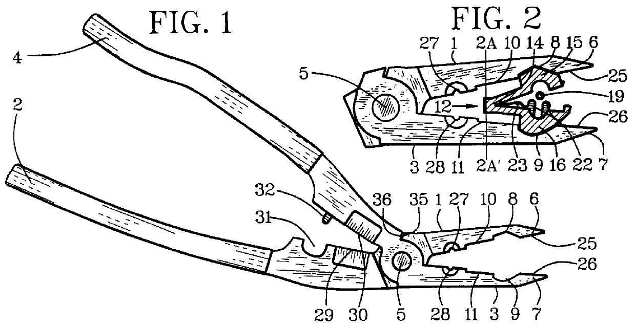
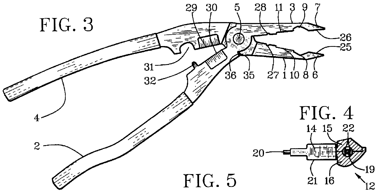
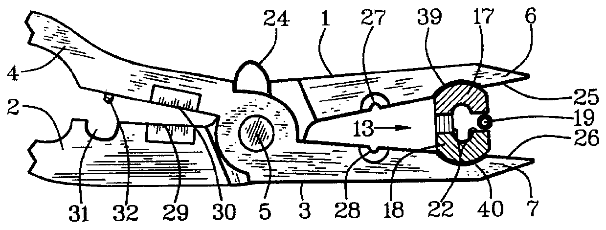
Reference is made first to FIGS. 1-6. A first jaw 1 and a first handle 2 are joined pivotally to a second jaw 3 and a second handle 4 with a pliers axle 5 at a pliers fulcrum axis. The first handle 2 and the second handle 4 are insulated. A first-jaw nose 6 is extended from the first jaw 1 and a second-jaw nose 7 is extended from the second jaw 3 at a nose of the pliers.

A T-fastener closer is positioned intermediate the pliers axle 5 and the nose of the pliers. A preferred embodiment of a T-fastener closer has a first grip bay 8 extended from an inside edge of the first jaw 1 and a second grip bay 9 extended from an inside edge of the second jaw 3. The first grip bay 8 and the second grip bay 9 are at designedly equal distances from the pliers axle 5 at positions intermediate a fulcrum axis and a nose of the pliers.

A first fastener-hinge notch 10 can be extended from an axle side of the first grip bay 8 and a second fastener-hinge notch 11 can be extended similarly from an axle side...


PUM


Abstract

An electrical T-fastener pliers has jaws (1, 3) with grip bays (8, 9, 39, 40) that are positioned on T-joint fastener jaws (15, 16, 17, 18) to be clamped onto targeted wires (19) by hand-squeezing handles (2, 4) of the electrical pliers. Jaws of the T-joint fasteners (12) are pressured against jaws of the pliers by outward pressure of outwardly sprung T-joint fasteners against designedly opened pliers jaws or optionally by inward pressure of the pliers jaws against jaws of unsprung T-joint fasteners (13). This provides a spring-pressured containment of a T-joint fastener while the pliers are being positioned in T-joining relationship to targeted electrical wiring. The handles can be extended at angles from the jaws to position a bottom handle designedly removed from a working surface in order to provide finger space between a working surface and in order to facilitate positioning the jaws under wires in close proximity to surfaces. Select wire-processor tooling such as wire strippers (27, 28, 33, 34), crimpers (31, 32) and wire cutters (29, 30) is provided on the jaws and on the handles for particular use conditions.

Description

1. Field of the InventionThis invention relates to hand-tool pliers and in particular to electrical pliers with which electrical-wire T-joint fasteners can be spring-pressure held without being dropped while being positioned and clamped onto targeted electrical wires.2. Relation To Prior ArtCurrently, there are no known electrical pliers having a T-joint closer with which electrical-wire T-joint fastener jaws can be held, positioned and clamped conveniently and efficiently onto targeted electrical wires in a manner taught by this invention. Conventionally, T-joint fasteners are hand-held and either hand-clamped or pressured together with variously inconvenient, awkward and ineffective means.Examples of different but related electrical pliers without T-joint closers are described in the following patent documents. U.S. Pat. No. 5,604,947, issued to Bates et al, described pliers that gripped and cut wire. U.S. Pat. No. 4,407,174, issued to Schulze, described wire-stripping pliers with...

Claims


Application Information

Patent Timeline
Patent Type & Authority Patents(United States)
IPC IPC(8): B25B7/00B25B7/22B25B7/02H01R43/042H01R43/04
CPCB25B7/02B25B7/22H01R43/0421
Inventor HAXTON, MICHAEL L.
Owner HAXTON MICHAEL L
Why Eureka
Try Eureka