Medicament dispensing cell

a technology of medicament dispensing and cell, which is applied in the direction of charge manipulation, instruments, furnaces, etc., can solve the problems of inaccurate counting of the photoelectric eye on the manipulator arm, the dispensing cell, and the present of problems

Inactive Publication Date: 2000-07-11
SCRIPTPRO L L C
View PDF23 Cites 126 Cited by
  • Summary
  • Abstract
  • Description
  • Claims
  • Application Information

AI Technical Summary

Problems solved by technology

While generally adequate, the dispensing cell as disclosed in the '919 patent presents some problems.
Additionally, medicament units are sometimes dispensed without adequate spacing therebetween resulting in an inaccurate count by the photoelectric eye on the manipulator arm.
Breaking and jamming of medicament units has also been a problem.

Method used


Image

  • Medicament dispensing cell
  • Medicament dispensing cell
  • Medicament dispensing cell

Examples


Embodiment Construction

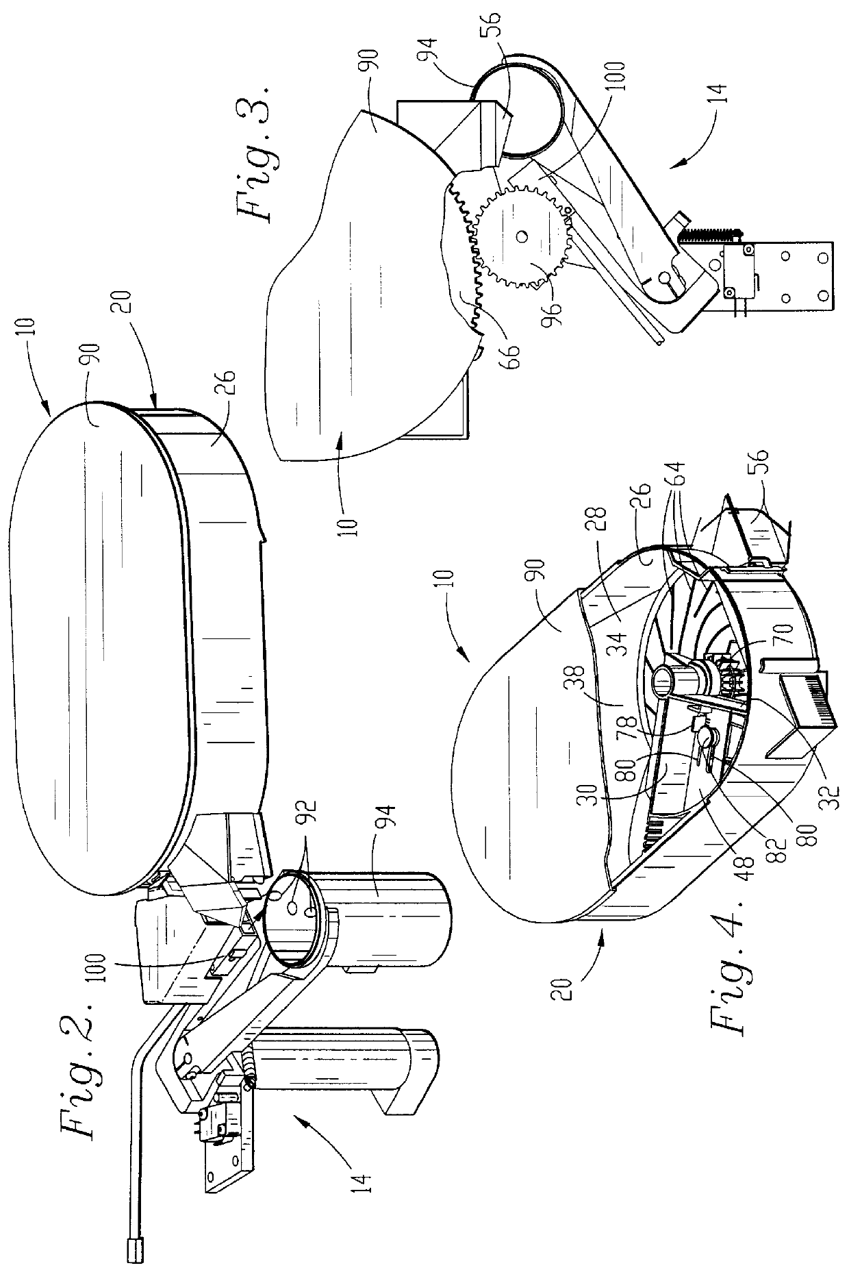
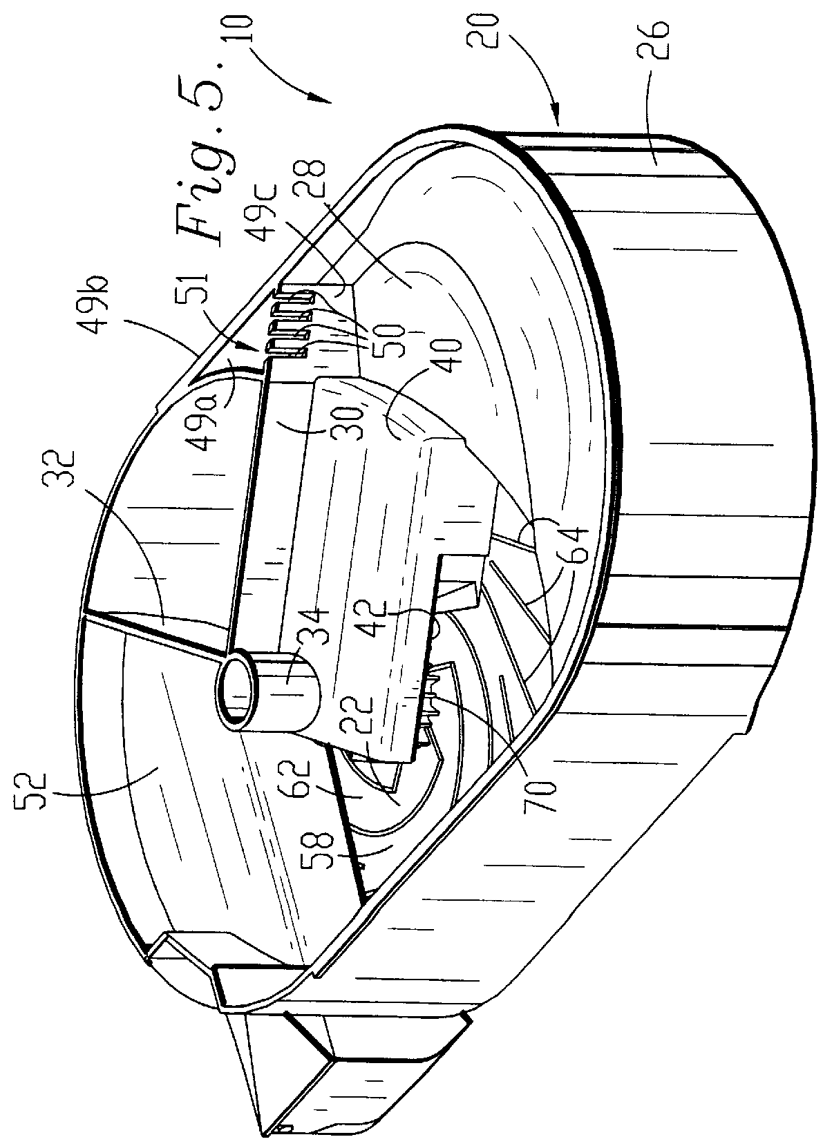
FIGS. 11-14 illustrate medicament dispensing cell 110 as another embodiment of the present invention. Cell 110 includes components similar to cell 10 and similar components bear the same numerical designations.

As best viewed in FIG. 11, channel wall 98 defines the outboard side of discharge section 44. As discussed above, the rotation of platen 22 conveys caplets 92 toward channel wall 98 during rotation of platen 22.

Dispensing cell 110 includes a pair of spacing fingers 112 and 114 preferably composed of resilient material such as MYLAR synthetic resin material. As best viewed in FIG. 13, fingers 112,114 are formed from a single sheet of material cut and scored to form the configuration illustrated. The sheet is then affixed to channel wall 98 so that fingers 112,114 extend into discharge section 44.

Fingers 112, 114 each presents a planar configuration and includes a first end 116 coupled with channel wall 98 and a distal end 118 positioned in discharge section 44. Each finger 112,...


PUM


Abstract

A medicament dispensing cell for use in an automatic dispensing machine includes a housing defining a medicament storage section, a discharge section leading to an outlet, a passage between the sections, a rotatable platen and a dispensing assembly for dispensing medicament in single file from the storage section to the discharge section. A pair of resilient, spacing fingers extend from the outboard wall of the discharge section and are positioned to guide medicament units around the distal end thereof in order to space medicament units during rotation of the platen.

Description

1. Field of the InventionThe present invention relates to the field of automatic medicament dispensing machines. In particular, the invention is concerned with a medicament dispensing cell for use in an automatic dispensing machine.2. Description of the Prior ArtU.S. Pat. No. 5,337,919 discloses an automatic medicament dispensing machine having a plurality of dispensing cells for storing and dispensing various types of solid medicament units such as pills, capsules and caplets. Each cell includes a rotatable platen presenting a driven gear. A manipulator arm of the machine retrieves an empty vial and positions the vial adjacent the outlet of a selected dispensing cell. The manipulator arm includes a drive gear that engages the driven gear of the cell for selective rotation thereof in order to dispense medicament from the cell. The filled vial is then positioned on a discharge conveyor for subsequent handling such as labeling and inspection.While generally adequate, the dispensing ce...

Claims


Application Information

Patent Timeline
Patent Type & Authority Patents(United States)
IPC IPC(8): A61J7/00G07F11/02G07F11/44
CPCG07F11/44G07F17/0092
Inventor COUGHLIN, SHANE P.
Owner SCRIPTPRO L L C
Why Eureka
Try Eureka