Battery cell bypass switch

a battery cell and switch technology, applied in the direction of protective switch operating/releasing mechanism, relay, contact mechanism, etc., can solve the problem of reducing the possibility of apparatus failure by substantial amoun

Inactive Publication Date: 2000-07-25
G&H TECH INC
View PDF1 Cites 35 Cited by
  • Summary
  • Abstract
  • Description
  • Claims
  • Application Information

AI Technical Summary

Problems solved by technology

Similarly, whereas the patented device includes a pair of plungers (36) and (136) which are individually operated, replacement with a single plunger assembly substantially reduces the possibility of apparatus failure.

Method used


Image

  • Battery cell bypass switch
  • Battery cell bypass switch
  • Battery cell bypass switch

Examples


Embodiment Construction

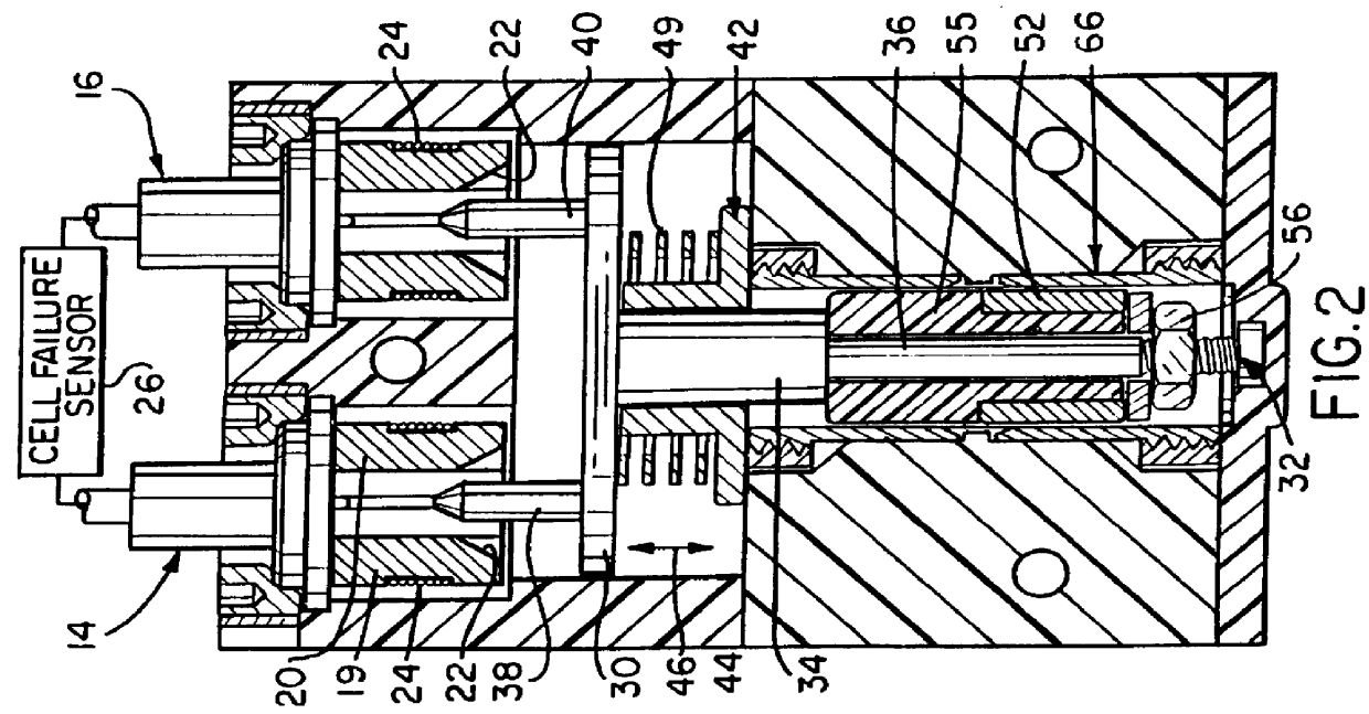
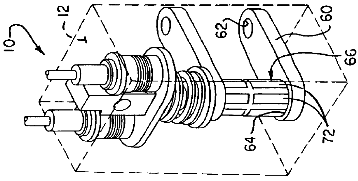
Turning now to the drawings, and particularly FIG. 1, the cell bypassing system of the present invention is shown enumerated generally as 10 and is seen to include a generally parallelepiped housing 12 within which the system parts are contained. Although other materials may be advantageously employed, the housing is preferably constructed of polyetherether ketone (PEEK) which is generally electrically non-conductive and has been found to possess higher temperature resistance than, say, teflon (which have been used for this purpose in the cited U.S. Pat. No. 5,438,173).

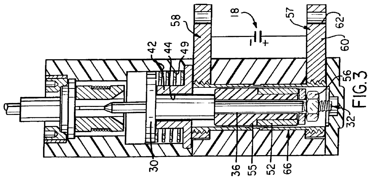
In what is the upper end portion shown in FIGS. 2 and 3, there are located first and second retaining means 14 and 16 which, as will be described, maintain the entire system 10 when in an "armed" MODE so as not to interfere with the normal electrical operation of the battery cell array, one cell of which array is shown and enumerated as 18. Since the retaining means 14 and 16 are identical, only means 14 will be descr...


PUM

PropertyMeasurementUnit
sizeaaaaaaaaaa
currentaaaaaaaaaa
timeaaaaaaaaaa

Abstract

A system (10) for establishing bypass of a failed battery cell (18) includes a failed cell sensor (26) which on sensing a failed cell generates an electric signal that destroys clamping relation of two retaining wire spools (24) to release retaining means (14,16). Such release enables a unitary plunger assembly (28) to be moved by a spring (49) to position a cylindrical pin contact (52) in electrical shorting relation to the first and second electrodes (57,58) connected across the cell (18).

Description

1. Background of the InventionThe present invention relates generally to a serial array of battery cells used in aerospace applications, and particularly to a system for shorting around or bypassing one of the cells in the serial array when it has failed thereby providing a continuous electrical battery circuit despite failure of one or more of the battery cells.2. Description of Related ArtU.S. Pat. No. 5,438,173, CELL BYPASS SWITCH, by Edward Rudoy and Leslie Kerek, assigned to the same assignee as the present application, relates generally to a cell bypass switch including a sensor for determining when a given battery has failed. This results in an alternate current path being established around the failed battery cell thereby permitting the remainder of the battery cells to continue their function. More specifically, the patented bypass switch includes a pair of collapsible collet fingers connected to an electrical pin contact which is positioned on the axis of a pair of socket ...

Claims


Application Information

Patent Timeline
Patent Type & Authority Patents(United States)
IPC IPC(8): H01H79/00H01H71/20H01H71/12
CPCH01H79/00H01H71/20
Inventor WU, JUI-YUDALTON, MATTHEW B.
Owner G&H TECH INC
Why Eureka
Try Eureka