Gearshift for bicycle gears

Inactive Publication Date: 2000-08-01
SRAM
View PDF10 Cites 50 Cited by
  • Summary
  • Abstract
  • Description
  • Claims
  • Application Information

AI Technical Summary

Problems solved by technology

The rotational axle for the release lever is integrated into the operating lever and, during shifting into individual speeds, rotates around the central axle of the operating lever, so that in the e

Method used


Image

  • Gearshift for bicycle gears
  • Gearshift for bicycle gears
  • Gearshift for bicycle gears

Examples


Embodiment Construction

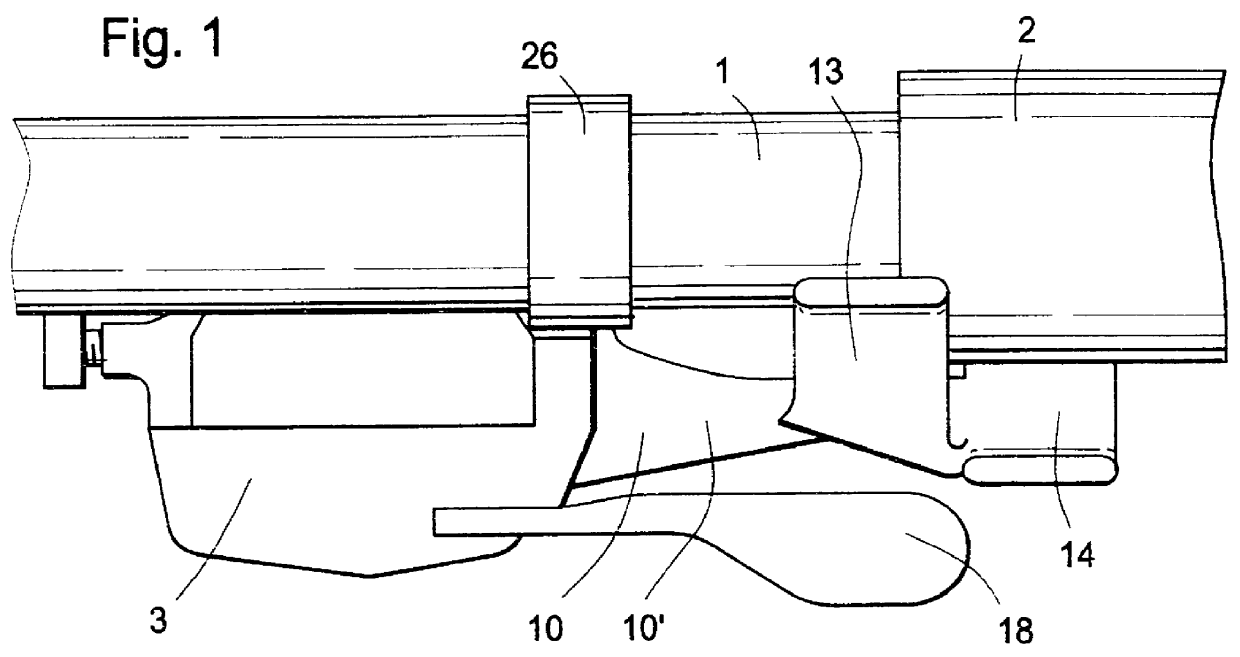
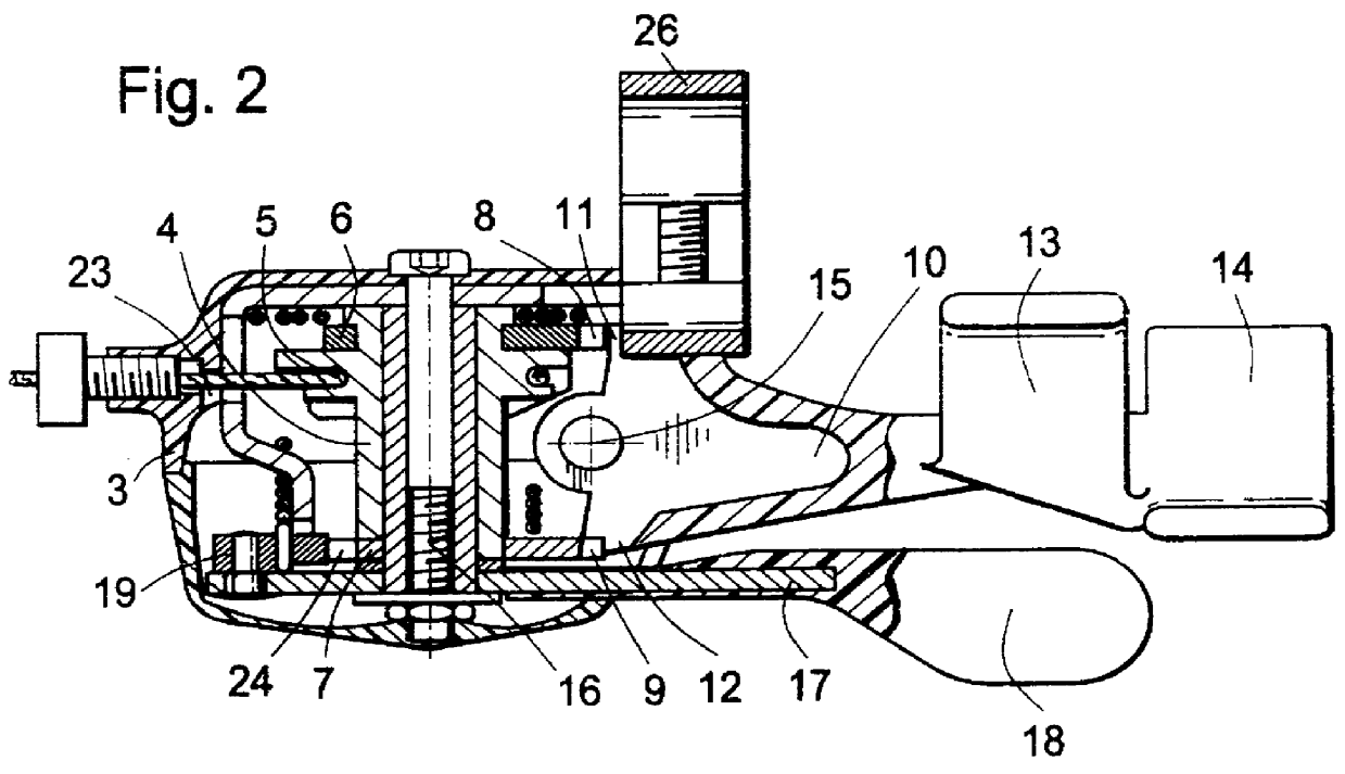
FIGS. 1 and 2 show a bicycle handlebar 1, on which is arranged a handle part 2 for the hand of the bicycle rider. A gearshift 3 is attached to the handlebar 1 by means of a clamp 26, and the housing 3 is arranged substantially below the handlebar 1. Arranged in the interior of the housing 3 is a central axle or axis 16, about which an operating part 4 can rotate. Defined on the operating part 4 is a take-up groove 5 for receiving a gear-shifting cable, which is connected to the bicycle gear and can enter the housing 3 via an opening 23.

The gearshift has a release-and-hold mechanism connected to the operating part 4. The release-and-hold mechanism includes a first latching disk 6 and a second latching disk 7. As shown, the first latching disk 6 has a first latching toothed segment 8 and is arranged at the upper end of the operating part 4. At the lower end of the operating part 4, i.e., the end remote from the handlebar, there is a second latching disk 7 having a second latching toot...


PUM


Abstract

A gearshift for bicycle gears includes an operating lever arranged so as to be rotatable around a stationary central axis for controlling an operating part arranged in a housing. The operating part is also rotatable around the central axis and has a take-up groove for receiving a gear-shifting cable, whereby a latch interacts with a tooth mechanism on the operating part for winding the cable. The gearshift further includes a release-and-hold mechanism consisting of a first latching disk having a first latching segment and a second latching disk having a second latching segment connected to the operating part, and of a release lever that interacts alternately with the first latching segment and the second latching segment. Arranged on the release lever are a first latching lug and a second latching lug, which alternately engage with the first latching segment and the second latching segment. The release lever is mounted pivotally about a rotational axis arranged substantially perpendicularly relative to the central axis in a stationary fashion. An advantage of the invention lies in the simple operability of the operating lever and the release lever, whereby attention has been given to the ergonomics of the lever that the bicycle gear can be shifted under any circumstances, even when the operating hand of a bicyclist is being used for operating a brake lever.

Description

1. Field of the InventionThe present invention relates to gearshifts for bicycles and, more particularly, a bicycle gearshift having an operating lever and a release lever.2. Description of the Related ArtEP 0 352 733 B1 discloses a gearshift for bicycle gears. The object of the aforementioned invention is to provide an improved gearshift (in this case, a trigger gearshift), in which the cable can be wound up against the spring of the bicycle gear and the release of the cable by a latching mechanism can be implemented by the operation of a single lever. This object is attained by an operating lever that, for the purpose of tensioning the cable, is mounted rotatably around a central axle, whereby a latching mechanism is passed through for each speed as the bicycle is shifted from speed to speed. The latching mechanism can be relieved of load by means of a release lever in such a way that the operating lever is drawn back from the cable into the next latching position for the next spe...

Claims


Application Information

Patent Timeline
IPC IPC(8): B62M25/04B62M25/00B62K23/06B62K23/00
CPCB62K23/06B62M25/04Y10T74/20438Y10T74/20287Y10T74/20043
Inventor ARBEITER, MARKUSASSEL, MARTIN
Owner SRAM
Why Eureka
Try Eureka