Joint seal and assembly method thereof

a joint seal and assembly method technology, applied in the direction of girders, other chemical processes, ways, etc., can solve the problems of limiting the insertion limit, allowing almost no freedom, and forcing the sealing material out of the heart wood

Inactive Publication Date: 2000-08-15
SEIKI IND
View PDF5 Cites 56 Cited by
  • Summary
  • Abstract
  • Description
  • Claims
  • Application Information

AI Technical Summary

Problems solved by technology

However, since the foregoing suggested joint seal is designed to adhere to and secure the base plate of the joint base directly to the bottom face of the joint groove, the arrangement encounters problems if the joint groove happens to be deep, with the sealing material tending to flow out when the heart wood is pressed into the space surrounded by the seal tongue piece at the upper part of the joint base material, the heart wood and the inner wall of the joint groove.
Therefore, in some cases the sealing material is not contained in that small space when the width of the joint groove is narrow and does not properly fit to the joint groove with various width.
The result may be that the sealing material is forced out of the heart wood.
This arrangement permits almost no freedom for relative displacement of the adjacent external wall material In an earthquake or other event that causes the wall materials to shift, the sealing material may be removed from the joint groove or parts of the joint broken.
Thus, even if friction between the seal tongue piece projecting from the outer face of the side plate and the inner face of the joint groove or the engaging and locking of the engagement collar portion against the opening edge of the joint groove is incomplete, the insertion limit is set by the foregoing stopper, and the joint base material is nerver pushed too far into the joint groove.

Method used


Image

  • Joint seal and assembly method thereof
  • Joint seal and assembly method thereof
  • Joint seal and assembly method thereof

Examples


first embodiment

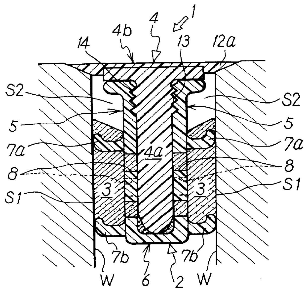
Preferred embodiments of the present invention are described in detail below with references to the drawings. FIG. 1 to FIG. 4 show the joint seal of the present invention.

This joint seal 1 is generally composed of a joint base material 2, a sealing material 3, and a heart wood 4, as seen from FIG. 1. Joint base material 2 and the heart wood 4 are of the sectional shapes described below and are provided in a long shape to facilitate easy assembly.

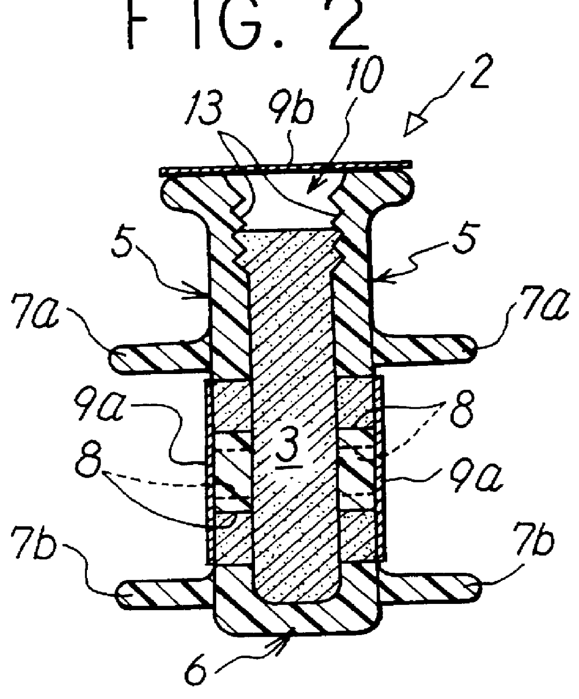
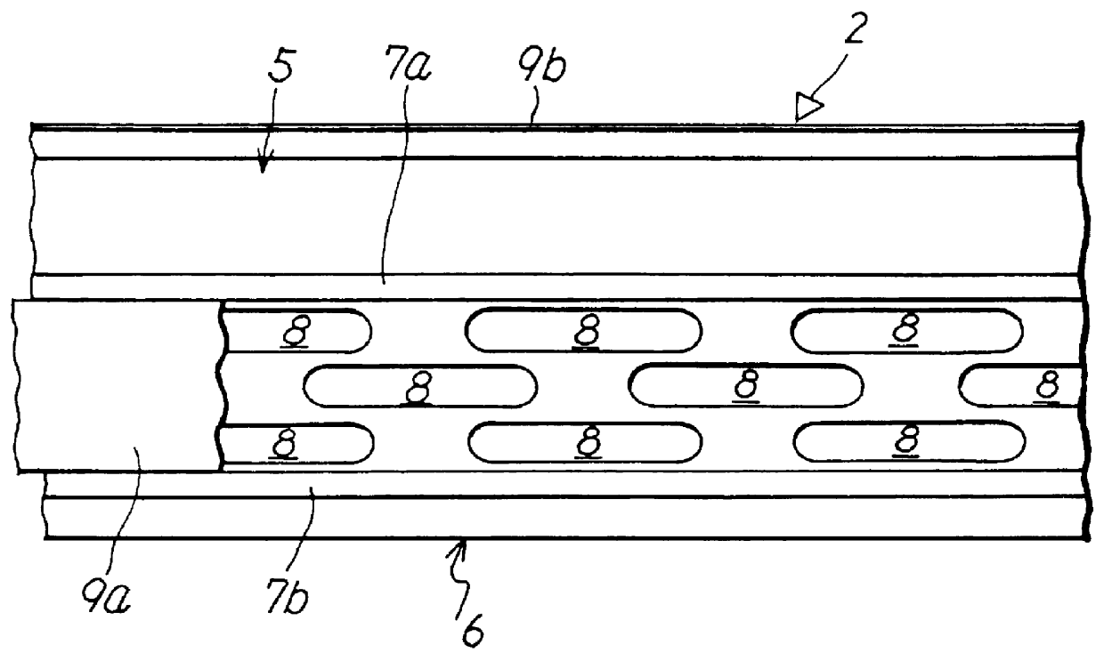
The foregoing joint base material 2 is molded into the sectional rough U shape while left and right side plates 5, 5 made of hard synthetic resin are coupled with corresponding integral base plate 6, as shown in FIGS. 2 and 3, and a pair of seal tongue pieces 7a and 7b made of soft synthetic resin is integrated with the project at the upper part and lower part of the side plates 5. Bottom plate 6 can be formed integrally with side plate 5 with soft synthetic resin, as required.

Sealing material 3 which has flow properties and viscosity is fo...

third embodiment

Joint seal 61 of the third embodiment having the foregoing configuration ensures against side plates 5, 5 in joint base material 2 being forced together, and the resultant outflow of sealing material 3 when joint base material 2 is engaged in the joint groove by inserting and engaging cap body 15 into opening port 10 of joint base material 2.

Other configuration details, effects and assembly methods for the third embodiment are largely identical to those of the foregoing first embodiment. The same reference numerals are given to the same or corresponding portions, and descriptions are omitted.

fourth embodiment

FIG. 8 to 10 illustrate the joint seal of the present invention.

A joint seal 91 of the fourth embodiment is integrally provided with engaging and locking collar portions 107, 107, made of synthetic resin to lock with the opening edge of the joint groove at the upper ends of left and right side plates 95, 95 in joint base material 92.

A heart wood 94 with an exterior plate 102 of head part 94b, similar to that in the foregoing first embodiment as shown in FIGS. 8 to 10, is made thinner than in the first embodiment, to a length core portion 94a reaches bottom plate 96 of joint base material 92. This change facilitates insertion between side plates 95, 95; and collar portions 108, 108, made of soft synthetic resin for pressing out sealing material 3, are integrally molded at some, including a position close to the tip of both side faces of core portion 94a.

The other main configuration of the fourth embodiment is largely identical to the foregoing first embodiment. However, in this fourt...


PUM

PropertyMeasurementUnit
shapeaaaaaaaaaa
widthaaaaaaaaaa
depthaaaaaaaaaa

Abstract

A joint seal is designed to maintain its proper position in the joint groove opening port to create an effective seal between the inner walls of the joint groove and to resist peeling or damage, even in an event, such as an earthquake, during which the adjacent outer wall materials shift; and to have a joint base material 2, a sealing material 3 and a heart wood 8. The joint base material 2 has at least two seal tongue pieces 14a and 14b projecting from the outer face of side plates 5, 5. A number of small openings 8 to allow sealing material to be pressed out at the insertion of heart wood 8 is punched between the seal tongue pieces 14a and 14b, and release mold sheets 18a and 18b are attached to joint base material 2 as a cap member covering the small openings 8 and the opening ports of side plates 5, 5.

Description

The present invention relates to a joint seal for a joint finish that is fitted in a joint groove opening port, as found in a joint section of a wall face exterior material of a building, and a method for assembling the joint seal.DESCRIPTION OF THE PRIOR ARTIt is well known that the joint seal disclosed in Japanese Patent Application No. 132104, 1994 is designed to permit a sealing material to flow from an opening port for heart wood insertion at the upper part of a joint base to both sides of the foregoing heart wood by engaging a joint seal filled with the sealing material in the joint groove opening port when the heart wood is pressed into the joint base.However, since the foregoing suggested joint seal is designed to adhere to and secure the base plate of the joint base directly to the bottom face of the joint groove, the arrangement encounters problems if the joint groove happens to be deep, with the sealing material tending to flow out when the heart wood is pressed into the ...

Claims


Application Information

Patent Timeline
Patent Type & Authority Patents(United States)
IPC IPC(8): E04B1/68E04B1/684E04B1/682
CPCE04B1/6816Y10S277/906E04B1/62E04B2/58
Inventor MORIYA, MAMORUHASEGAWA, KENICHI
Owner SEIKI IND
Why Eureka
Try Eureka