
Rack for a switching cabinet

a switching cabinet and rack technology, applied in the field of racks for switching cabinets, can solve the problem of not being able to see into the runoff channel from the outsid

Inactive Publication Date: 2000-08-15
RITTALWERK RUDOLF LOH GMBH & CO KG
View PDF9 Cites 40 Cited by
  • Summary
  • Abstract
  • Description
  • Claims
  • Application Information

AI Technical Summary

Problems solved by technology

This edge prevents impurities from entering the runoff channel and provides an optical closing arrangement, so that it is not possible to see into the runoff channel from the outside.

Method used


Image

  • Rack for a switching cabinet
  • Rack for a switching cabinet

Examples


Embodiment Construction

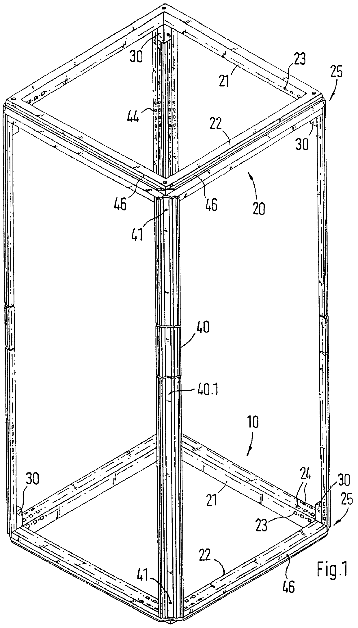
In FIG. 1, a rack for a switching cabinet is shown. The switching cabinet comprises a lower frame (10), an upper frame (20) and four vertical frame profiles (40). The vertical frame profiles (40) connect the lower frame (10) to the upper frame (20). The lower and upper frames (10 and 20) are identically constructed so that they are interchangeable.

The lower and the upper frames (10 and 20), respectively, have two longitudinal struts and two lateral struts (21, 22). The struts (21, 22) have on their profiled sides facing the interior of the rack rows of attachment mountings (23, 24). Also the vertical frame profiles (40) have attachment mountings (44) facing toward the interior of the rack. On the attachment mountings (23, 24, 44), electrical installations or mounting aids, such as mounting rails, can be attached.

The vertical frame profiles (40) are connected by connectors (30) to the lower or upper frames (10, 20). The connectors (30) are arranged in an area of the corner mountings ...


PUM


Abstract

PCT No. PCT / EP97 / 06151 Sec. 371 Date May 14, 1999 Sec. 102(e) Date May 14, 1999 PCT Filed Nov. 6, 1997 PCT Pub. No. WO98 / 23009 PCT Pub. Date May 28, 1998A rack for a switching cabinet which can be enclosed by side walls, at least one door and a cover and comprises a lower and upper frame which can be connected by frame profiles running vertically. The upper frame has vertical and horizontal struts running horizontally. The vertical and lateral struts include channels where water that runs off from the cover can be collected and drained. Water can then be drained off from the corner areas of the upper frame in a controlled manner if the outlet channels of adjacent vertical and horizontal struts are brought together and fed to a flume of the vertical frame piece.

Description

1. Field of the InventionThis invention relates to a rack for a switching cabinet which can be enclosed by side walls, at least one door and a lid and which has a lower frame and an upper frame that can be connected by vertically extending frame profiles, wherein the upper frame has longitudinal struts and lateral struts running horizontally and the struts have runoff channels so that water running off the lid can be collected and drained.2. Description of Prior ArtSuch a rack is known from European Patent Reference EP 0 402 276. With such racks, the upper frame consists of two struts, respectively. These are in the form of hollow profile sections which are connected at their ends at a right angle. For the connection, there is a corner-connecting part to which the struts can be screwed. The corner-connecting part has a receptacle element which is open to the outside and into which a second corner-connecting part can be introduced. At the second corner-connecting part, the vertical f...

Claims


Application Information

Patent Timeline
IPC IPC(8): H02B1/30H02B1/28H02B1/00H05K7/18
CPCH02B1/28H02B1/30H02B1/301
Inventor KOHLER, MARTINAREUTER, WOLFGANG
Owner RITTALWERK RUDOLF LOH GMBH & CO KG
Features
  • Generate Ideas
  • Intellectual Property
  • Life Sciences
  • Materials
  • Tech Scout
  • Unparalleled Data Quality
  • Higher Quality Content
  • 60% Fewer Hallucinations
Learn More