Structural member with strength-reinforcing steel strap

Inactive Publication Date: 2000-09-05
BRASINGTON MILLARD A
View PDF19 Cites 2 Cited by
  • Summary
  • Abstract
  • Description
  • Claims
  • Application Information

AI Technical Summary

Benefits of technology

is to create a maximum supporting reaction force at a predetermined location between the ends of the structural member in a manner that will not significantly increase the weight and / or cost of the member. The invention will double the span of the structural member without reducing its load-bearing capacity. For example, a standard 24 foot beam has a maximum supporting reaction force at its supported ends and a minimum supporting reaction force at its center point 12 feet from either end. Longer beams have less strength at the center point, and must therefore be made of a heavier gauge steel or must include separately attached reinforcing structure which can substantially increase the overall weight and cost of the beam. The present invention adds low cost, lightweight reaction support at the center point of the beam, thereby shifting the area of less strength to respective mid-points between the center and ends of the beam.
As shown in FIG. 7, the longitudinal side edges of the flange members 41 and 42 have integrally formed hooks 44 and 45 which mate with complementary hooks 46 and 47 formed with the top and bottom panels 32A and 32B. The complementary hooks 44, 45, 46, and 47 allow ready and convenient assembly of the structural member 30 without risking penetration of the tensioned strap 35 with fasteners entering through the panels 32A, 32B and into the flange members 41 and 42.

Problems solved by technology

Longer beams have less strength at the center point, and must therefore be made of a heavier gauge steel or must include separately attached reinforcing structure which can substantially increase the overall weight and cost of the beam.
Cable tendons, however, are costly and generally too elastic to maintain proper tension over time.
This is not an option with light-gauge structural members.

Method used


Image

  • Structural member with strength-reinforcing steel strap
  • Structural member with strength-reinforcing steel strap
  • Structural member with strength-reinforcing steel strap

Examples


third embodiment

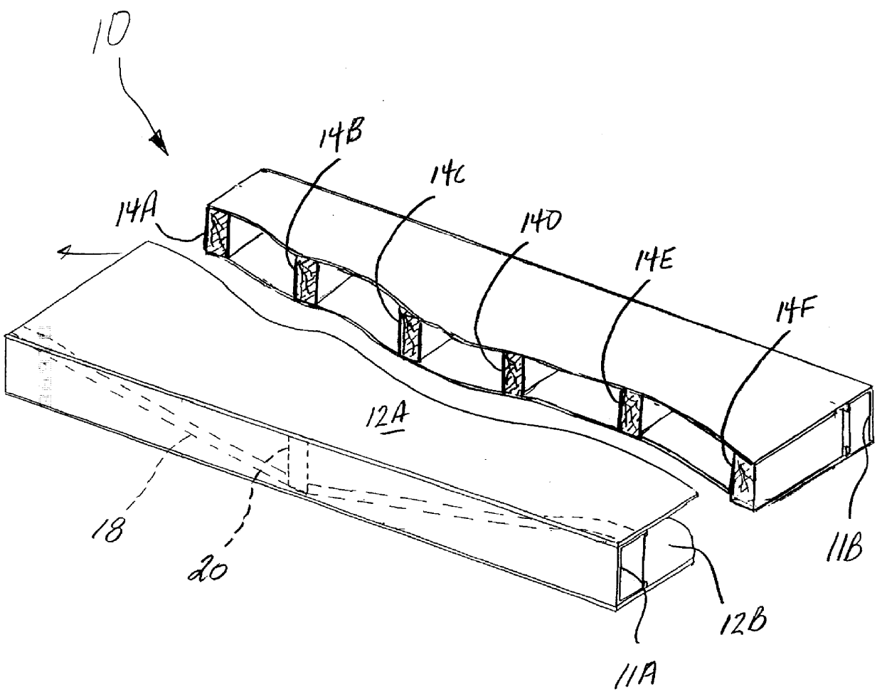
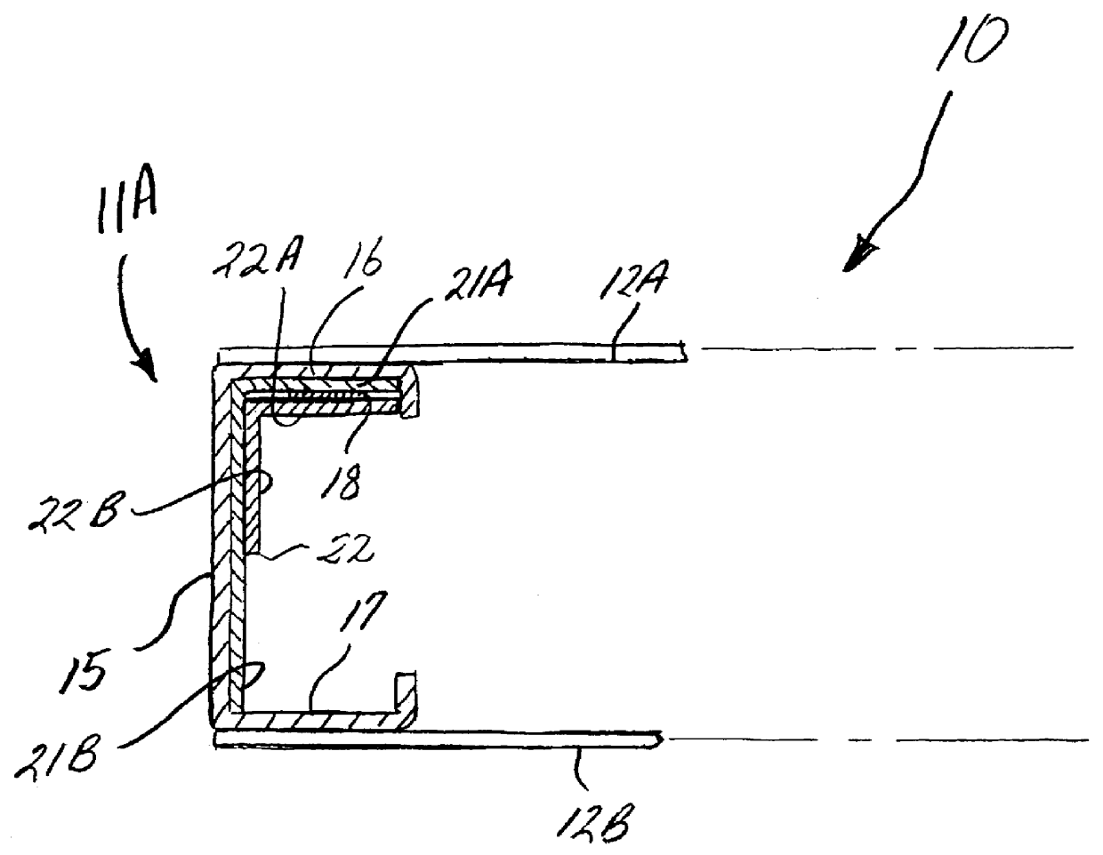
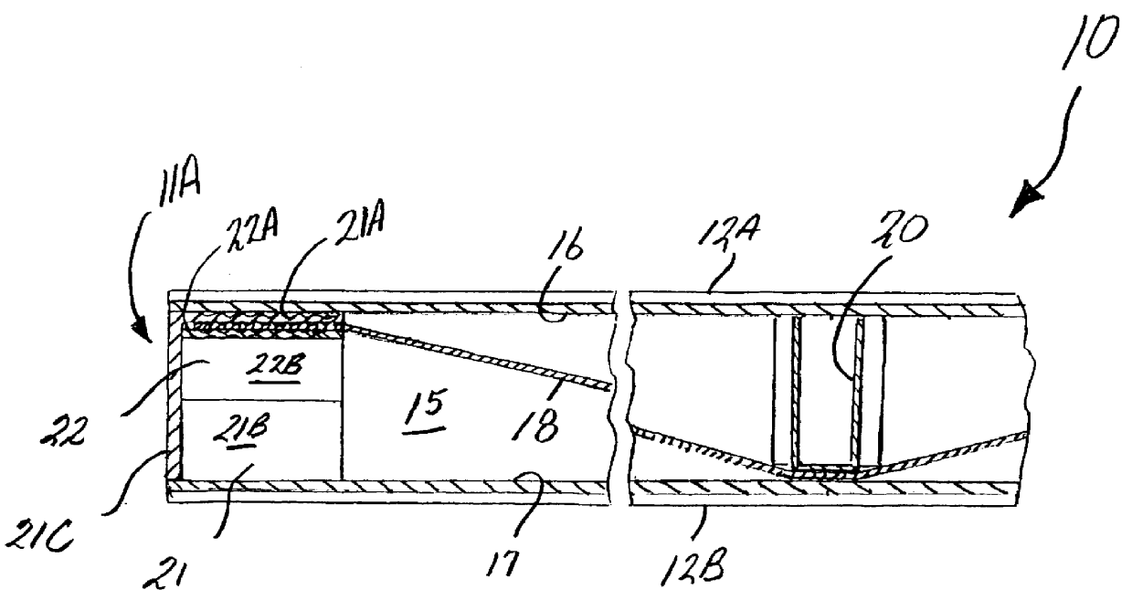
a structural member 50 forming a beam assembly according to the present invention is shown in FIGS. 8-11. The structural member 50 is constructed of a light-gauge steel beam 51 having a generally V-shaped or U-shaped cross-section. The range of steel thickness is preferably between 16 and 20 gauge. The beam 51 includes a bottom 52, opposing sides 53 and 54 integrally-formed with the bottom 52, and respective flanges 55 and 56 integrally-formed with the sides 53 and 54. The flanges 55 and 56 preferably include longitudinal fastener grooves 58 (See FIG. 11) for guiding suitable fasteners used for attaching the structural member 50 to other building members. The longitudinal edges 61 and 62 of the flanges 55 and 56 are folded downwardly to provide increased compression strength. A flat, pretensioned, stress-proof steel strap 64 is secured in tension to opposing ends of the beam 51 by cooperating pairs of anchor plates 66, 67 and 68, 69. The strap 64 is pulled downwardly at a center poi...


PUM

PropertyMeasurementUnit
Fractionaaaaaaaaaa
Tensile strengthaaaaaaaaaa
Lengthaaaaaaaaaa

Abstract

A load-bearing structural member includes an elongate beam and a strength-reinforcing flat steel strap. The beam has a top and a bottom, and first and second opposing ends. The steel strap extends along the length of the beam from one end to the other, and is adapted for transferring an intermediate load acting on the beam outwardly to the opposing ends of the beam. Anchor plates located at respective opposing ends of the beam engage and hold the strap in tension.

Description

TECHNICAL FIELD AND BACKGROUND OF THE INVENTIONThis invention relates to a load-bearing structural member. The structural member includes one or more strength-reinforcing, tensioned steel straps adapted for transferring an intermediate lateral load acting on the member to its supported ends. The invention is applicable to standard light-gauge steel C-channels, U-channels, Z-purlins, I-beams, and girts, square tubing, and light-gauge prefabricated building sections, such as floor trusses, stud or curtain walls, and roof panels. The invention provides a lightweight structural member with an extended span reach, and which is less costly and more functional than existing structures of equivalent strength and span.A principle object of the invention is to create a maximum supporting reaction force at a predetermined location between the ends of the structural member in a manner that will not significantly increase the weight and / or cost of the member. The invention will double the span o...

Claims


Application Information

Patent Timeline
IPC IPC(8): E04C3/10E04C3/04
CPCE04C3/10E04C2003/0413Y10T29/49629E04C2003/0473Y10T29/49634E04C2003/0434
Inventor BRASINGTON, MILLARD A.
Owner BRASINGTON MILLARD A
Why Eureka
Try Eureka