
Suction-type hand for drawing and holding workpiece

Active Publication Date: 2017-05-11
FANUC LTD
View PDF0 Cites 4 Cited by
  • Summary
  • Abstract
  • Description
  • Claims
  • Application Information

AI Technical Summary

Benefits of technology

The present invention is about a new tool that can hold and hold a curved surface workpiece. This tool is designed to reduce the weight and cost of traditional tools.

Problems solved by technology

However, when the position of each suction part 102 is maintained by the torque of the motor, new problems that will be described below arise.
This increases moment acting on the motor, and increases the torque required for the motor.
Consequently, the size and weight of the motor may increase, and the weight and cost of the hand 100 may increase.

Method used


Image

  • Suction-type hand for drawing and holding workpiece
  • Suction-type hand for drawing and holding workpiece
  • Suction-type hand for drawing and holding workpiece

Examples


Embodiment Construction

[0021]Embodiments of the present invention will be described below with reference to the drawings. In the following figures, similar members are designated with the same reference numerals. The members in the different figures, which are designated with the same reference numerals, represent components having the same function. These figures are properly modified in scale to assist the understanding thereof. Note that, in the following embodiments, a suction-type hand used as a robot hand of an industrial robot will be described. However, the suction-type hand according to the present invention can be used for any machines or devices for transferring a workpiece.

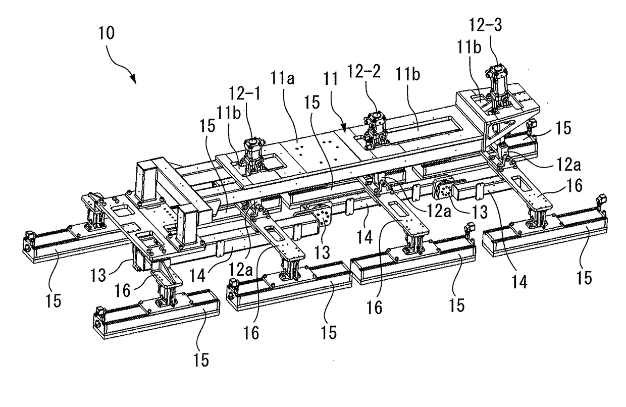
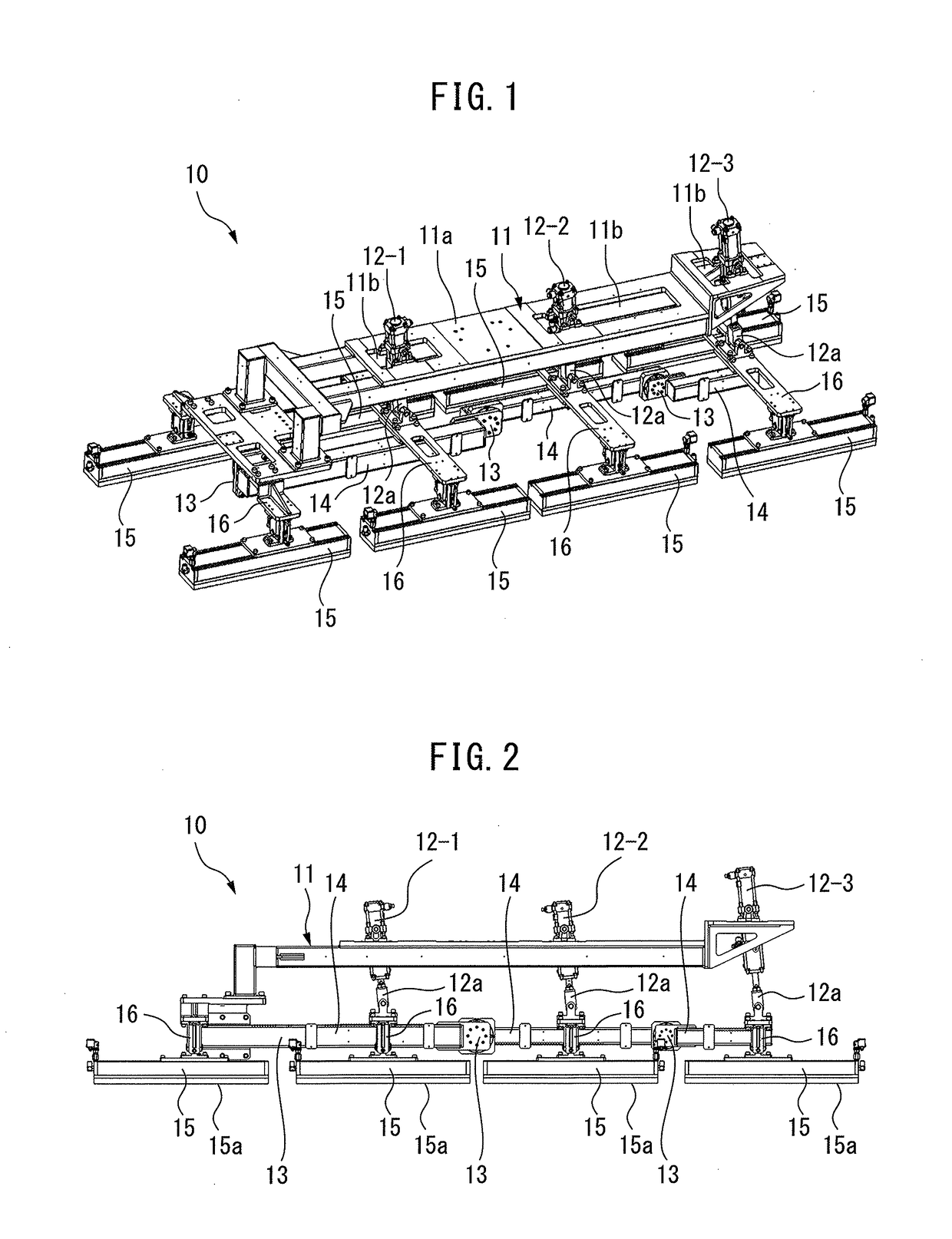
[0022]FIG. 1 is a perspective view of an embodiment of a suction-type hand according to the present invention. FIG. 2 is a side view of an embodiment of a suction-type hand according to the present invention.

[0023]With reference to FIGS. 1 and 2, a suction-type hand 10 according to the present embodiment is provided with a b...


PUM


Abstract

A suction-type hand according to the present invention includes a base part, a plurality of linear drive devices successively arranged in the base part, a plurality of link parts, which are each connected to the corresponding one of movable parts of the linear drive devices and which are moved closer to or moved away from the base part in response to the movement of the movable parts, a plurality of joint parts for connecting the plurality of link parts in series, and rotatably supporting the link parts, and a plurality of suction parts for drawing and holding a workpiece, which are each supported by the corresponding one of the plurality of link parts.

Description

BACKGROUND OF THE INVENTION[0001]1. Field of the Invention[0002]The present invention relates to a suction-type hand for drawing and holding a workpiece. In particular, the present invention relates to a suction-type hand for drawing and holding a workpiece to be transferred, which is used in an industrial robot.[0003]2. Description of the Related Art[0004]Suction-type hands for drawing and holding a workpiece have been known as robot hands used in industrial robots. In particular, suction-type hands for drawing and holding a workpiece by a suction part having suction holes through which a vacuum generator sucks air have been conventionally proposed.[0005]For example, Japanese Patent Application Laid-open Nos. 2000-079590 and 2007-221031 disclose a suction-type hand in which suction parts for drawing and holding a workpiece are arranged in a plane. However, when the surface of the workpiece is curved, gaps are developed between the surface of the workpiece and the suction parts, and...

Claims


Application Information

Patent Timeline
IPC IPC(8): B25J15/06B25J15/00
CPCB25J15/0052B25J15/0616B25J15/0028B66C1/0243
Inventor MUKOU, HIROSHIOCHIISHI, YOSHINORI
Owner FANUC LTD
Learn More