
Ultrasonic sensor

Inactive Publication Date: 2012-09-27
PANASONIC INTELLECTUAL PROPERTY MANAGEMENT CO LTD
View PDF11 Cites 9 Cited by
  • Summary
  • Abstract
  • Description
  • Claims
  • Application Information

AI Technical Summary

Benefits of technology

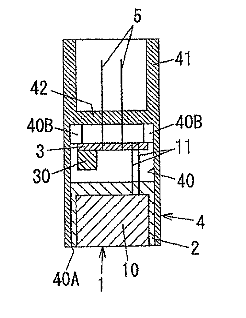
[0007]In view of the above, the present invention provides an ultrasonic sensor capable of securing a waterproof property without having to increase the number of parts, capable of suppressing an increase in weight and cost and capable of preventing generation of distortions in a circuit board.
[0010]With such configurations, the circuit board is stored within the single storing portion and the opening of the storing portion is closed by the transceiver block. It is therefore possible to secure a waterproof property without having to increase the number of parts, to suppress an increase in weight and cost and to prevent generation of distortions in a circuit board.

Problems solved by technology

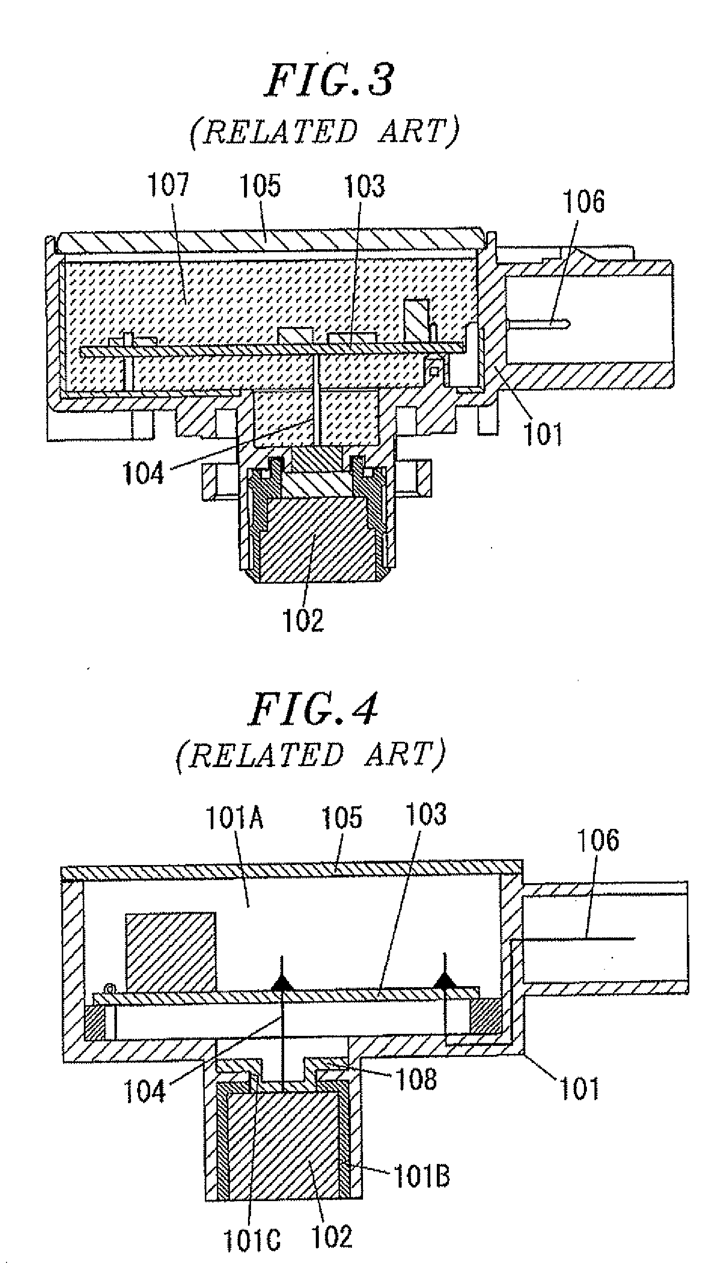
In the conventional example stated above, however, the weight and cost of the ultrasonic sensor is proportionately increased as the filler material 107 is filled in the housing 101.
If the distortions are generated, it is likely that stresses are applied to the solder portions between the circuit board 103 and the electronic parts mounted on the circuit board 103, consequently generating cracks in the solder portions.
This poses a problem in that the number of parts grows larger.
In addition, the costs such as equipment costs are necessarily increased in order to join the cover member 105 to the peripheral edge of the opening of the housing 105.
This leads to a problem in that the costs such as depreciation expense grow higher.

Method used


Image

  • Ultrasonic sensor
  • Ultrasonic sensor
  • Ultrasonic sensor

Examples


Embodiment Construction

[0016]One preferred embodiment of an ultrasonic sensor of the present invention will now be described with reference to the accompanying drawings. In the following description, the upper, lower, left and right sides in FIG. 1 will be defined as upper, lower, left and right directions.

[0017]Referring to FIG. 1, the ultrasonic sensor of the present embodiment includes a transceiver block 1 for transmitting and receiving ultrasonic waves, a cover 2 covering the outer circumferential surface of the transceiver block 1 except for the transceiving surface thereof and a circuit board 3 mounted with an electronic circuit for processing ultrasonic signals transmitted and received through the transceiver block 1. The ultrasonic sensor further includes a housing 4 having a storing portion 40 for accommodation of the circuit board 3. The storing portion 40 has an opening 40A. The ultrasonic sensor further includes a pair of outer connection terminals 5 connected at one end to the circuit board ...


PUM


Abstract

An ultrasonic sensor includes a transceiver block having a transceiver device for transmitting and receiving ultrasonic waves, and a circuit board mounted with an electronic circuit for processing ultrasonic signals transmitted and received through the transceiver device. A housing of the ultrasonic sensor includes a storing portion having an opening. The circuit board is stored within the storing portion, and the opening of the storing portion is closed by the transceiver block.

Description

FIELD OF THE INVENTION[0001]The present invention relates to an ultrasonic sensor that is mounted on, e.g., a motor vehicle to be used for obstacle detection or the like.BACKGROUND OF THE INVENTION[0002]Conventionally, there is available an ultrasonic sensor that includes, as shown in FIG. 3, a hollow housing 101 having an opening on one surface thereof and a transceiver device (transceiver block) 102 having a transceiving surface for transmitting and receiving ultrasonic waves, the transceiving surface exposed on the other surface of the housing 101. The ultrasonic sensor includes a circuit board 103 arranged within the housing 101 and mounted with an electronic circuit for processing ultrasonic waves transmitted and received through the transceiver device 102 and a wiring line 104 electrically interconnecting the transceiver device 102 and the circuit board 103. The ultrasonic sensor further includes a cover member 105 provided to cover the opening of the housing 101 and a termina...

Claims


Application Information

Patent Timeline
IPC IPC(8): G01N29/00
CPCG10K11/004G01S7/521
Inventor URASE, HIROSHINAGANO, YASUSHI
Owner PANASONIC INTELLECTUAL PROPERTY MANAGEMENT CO LTD
Learn More