

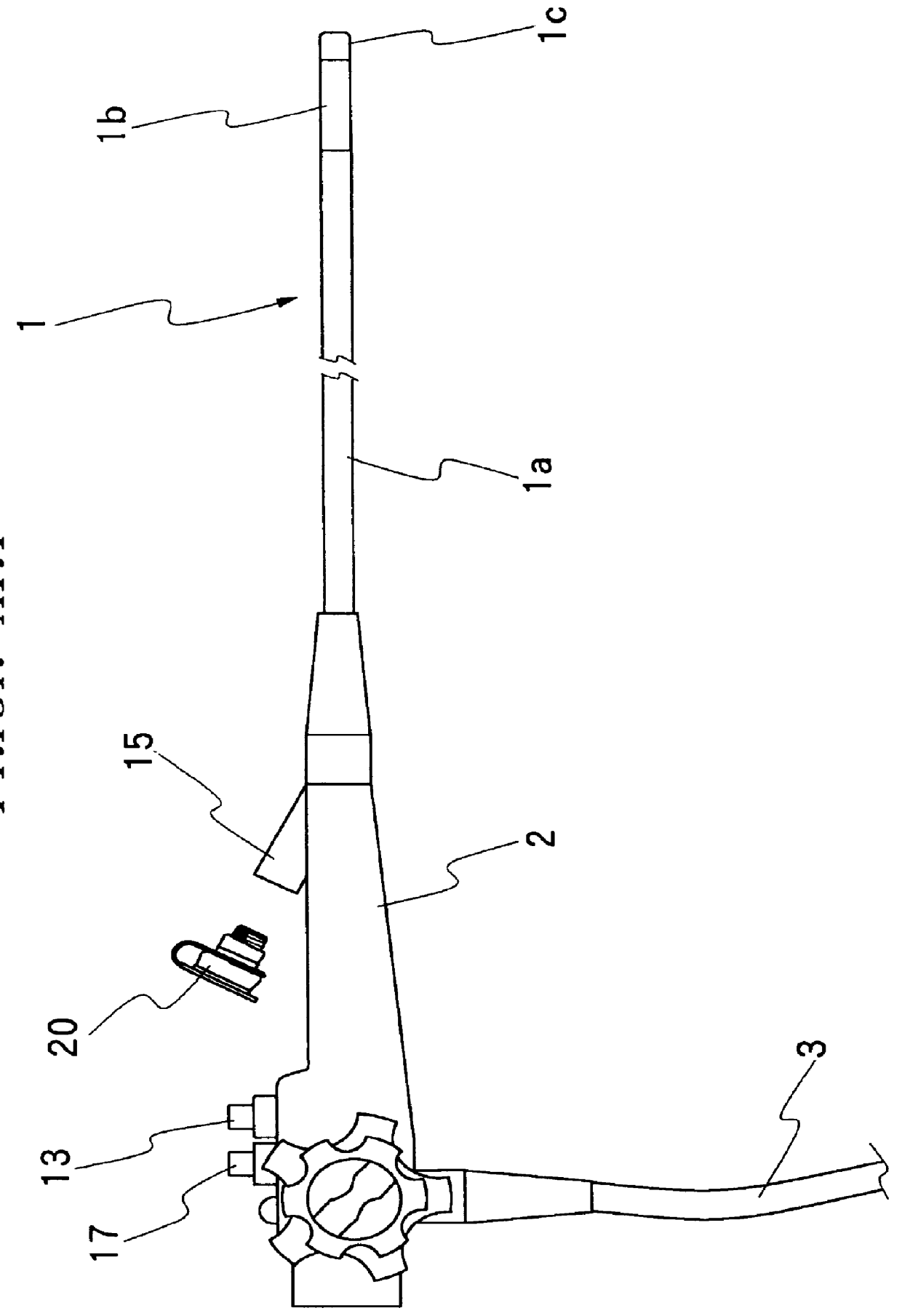
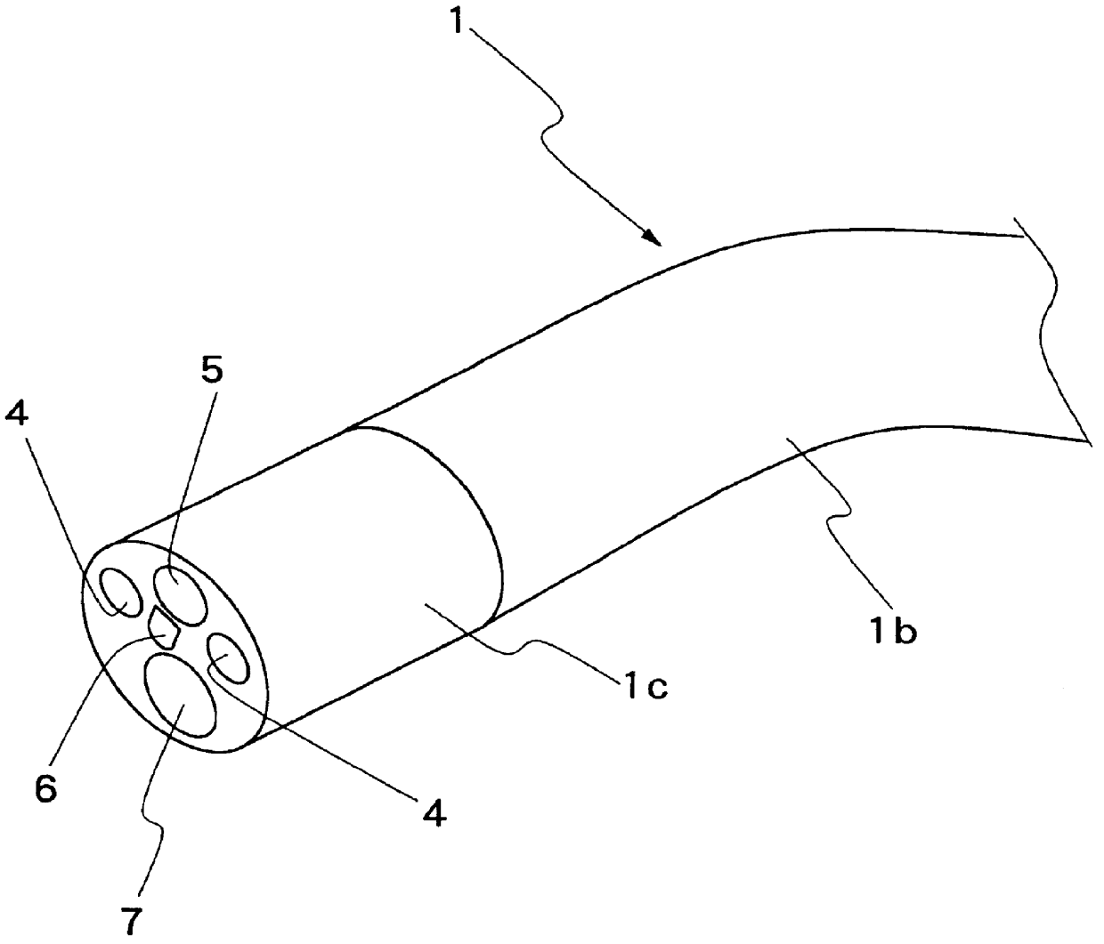
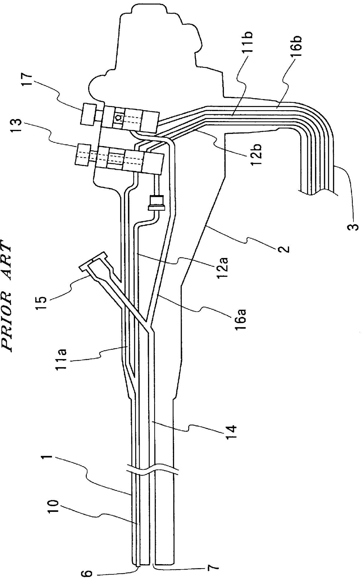
Plug device for endoscopic instrument channel
- Summary
- Abstract
- Description
- Claims
- Application Information
AI Technical Summary
Problems solved by technology
Method used
Image

Examples
second embodiment
Even when the plug device is arranged as in the above-described second embodiment, it can provide the same pressure relieving function to reduce the pressure difference of the instrument channel, by means of the pressure relief chamber 46 of the pressure relief member 43, in cooperation with the first and second throttle portions 47 and 48 at the outer and inner boundaries of the pressure relief chamber 46, when a thick treating instrument is inserted into the instrument channel, and by means of the inner space of the pressure relief member 43 including the pressure relief chamber 46, in cooperation with the slit 45 and the second throttle portion 48 at the outer and inner boundaries of its inner pressure relieving space, when a thin treating instrument is inserted into the instrument channel. Besides, the second throttle portion 48 which is constituted by an annular protuberance in this case can guarantee higher durability, restoring its original state smoothly even after repeated ...
third embodiment
Further, illustrated in FIG. 9 is a plug device 50 according to the present invention, in which a valve portion is arranged to serve also as a second throttle portion. More specifically, in this case, an outer shell member 51 contains a valve member 52 which can function as a valve member and at the same time as a pressure relief member. The valve member 52 is formed of a resilient material and provided with a first throttle portion 52 in the entrance passage of treating instruments, the throttle portion 52 having an aperture of such a diameter as to just fit on the circumference of a thick treating instrument substantially without leaving a gap space therearound. Formed on the inner side of the first throttle portion 54 is a pressure relief chamber 54 with a relatively broad space, and further formed on the inner side of the pressure relief chamber 54 is a thin concave wall portion 55 with a slit 56 which plays a dual as a valve and a second throttle portion.
With the arrangements j...
PUM
 Abstract
Description
Claims
Application Information