Receptacle including an anti-spill piece, and an anti-spill piece

a technology of anti-spill pieces and receptacles, which is applied in the direction of brushes, bottles, containers, etc., can solve the problems of not being able to obtain such a shutter, and not being able to envisage using such a shutter

Inactive Publication Date: 2000-10-17
LOREAL SA
View PDF11 Cites 18 Cited by
  • Summary
  • Abstract
  • Description
  • Claims
  • Application Information

AI Technical Summary

Benefits of technology

An object of the invention is to prevent substance from spilling out of the receptacle in the event of it being overturned accidentally, but without thereby influencing the way in which the substance is taken by the applicator.
the bottle can be made without increasing its cost, thereby making the use of such an anti-spill piece economically advantageous.

Problems solved by technology

Nevertheless, it is not possible to envisage using such a shutter when it is desirable to avoid wiping the applicator element, or indeed when it is desirable to wipe the applicator element, but to do so in a special manner that cannot be obtained if the applicator element needs to pass through the above-specified shutter.

Method used


Image

  • Receptacle including an anti-spill piece, and an anti-spill piece
  • Receptacle including an anti-spill piece, and an anti-spill piece
  • Receptacle including an anti-spill piece, and an anti-spill piece

Examples


first embodiment

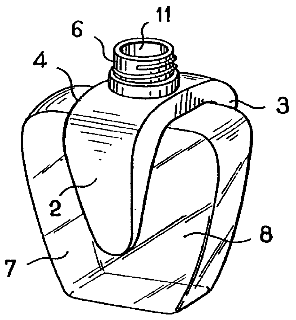
FIG. 1 shows an anti-spill piece 1 constituting the invention.

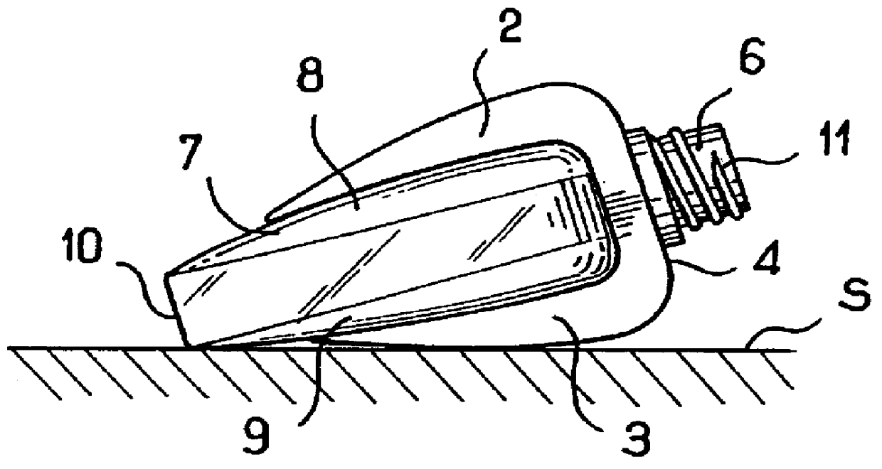
The piece 1 is horseshoe-shaped, having two side portions 2, 3 united by a top portion 4 through which there passes a hole 5 for receiving the neck 6 of a bottle 7, as shown in FIG. 2.

The bottle 7 is of a generally flat shape and it is made of plastics material or glass.

The bottle 7 preferably contains a viscous substance that does not splash in the event of the bottle being accidentally overturned.

The facing faces of the side portions 2 and 3 are shaped to fit closely over relief on the opposite main faces 8 and 9 of the bottle 7.

The anti-spill piece 1 can be fixed on the bottle 7 by adhesive for example, or in a variant the anti-spill piece 1 can be held merely by friction.

The neck 6 is threaded so as to receive a screw cap for closure purposes (not shown), which cap also serves as a handle for an applicator such as a brush, for example, which applicator is received inside the bottle 7 when it is closed.

The bottle 7 has...

third embodiment

FIGS. 6 to 8 show a receptacle 20 constituting the invention.

This receptacle 20 comprises a body 21 fitted at one end with a threaded neck 22 and at its other end with an outwardly convex bottom 23.

An anti-spill piece 24 is fitted to the body 21 at the base of the neck 22.

The anti-spill piece 24 is, for example, stuck to the body 21 of the receptacle.

A closure cap 25 is screwed onto the neck 22 to close it.

The closure cap 25 also serves as a handle for an applicator comprising a stalk 26 fixed at one end to the cap 25 and provided at its other end with an applicator member such as a brush 27.

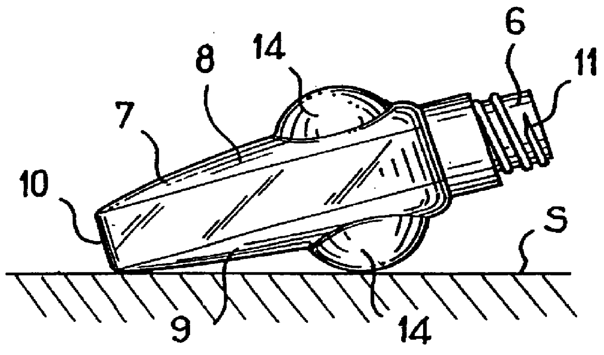
The body 21 may contain one or more beads 28 enabling the substance to be homogenized prior to application, e.g. on the fingernails.

The anti-spill piece 24 is in the form of a ring that projects radially outwards and whose surface is generally convex.

The bottom 23 prevents the receptacle 20 from standing upright.

When the receptacle 20 is placed on a plane surface S, it rests with its axis pointi...

eighth embodiment

FIG. 16 shows an anti-spill piece 80 constituting the invention.

This anti-spill piece 80 comprises two portions 81 and 82 for assembling around the bottle, e.g. the bottle 7 as described above.

The portions 81 and 82 are connected together at one end by a hinge 83 and each of them has a coupling 84 or 85 at its end remote from the hinge 83.

The couplings 84 and 85 are designed to form a collar around the neck 6 of the bottle 7 when the portions 81 and 82 are assembled against each other, as shown in FIG. 17.

The couplings 84 and 85 are connected to the hinge 83 via respective sets of bars referenced 86 for the portion 81 and 87 for the portion 82.

When the portions 81 and 82 are closed around the bottle 7, the bars 86 and 87 of the anti-spill piece 80 constitute a cage protecting the bottle 7 from shock and holding the opening of the neck 6 above the level of the liquid in the bottle 7, when filled to a given level. The cage can be made of elastically deformable material.

The anti-spill ...


PUM


Abstract

A receptacle comprising an applicator and a body forming a reservoir suitable for containing a fluid substance, said body being provided with a top opening. The receptacle includes at least one anti-spill piece fitted to the outside of said body, said piece being suitable for holding the opening of the body of the receptacle above the level of the liquid in the body of the receptacle when the receptacle is resting on a plane surface.

Description

The present invention relates to receptacles provided with a top opening and more particularly, but not exclusively, receptacles having an applicator comprising a stalk provided at one end with a handle member that also constitutes a closure cap, and having at its other end an applicator element.Such receptacles are used for packaging liquids such as nail polish, for example.U.S. Pat. No. 3,146,806 proposes inserting a shutter in the neck of a receptacle, the shutter being constituted by a disk that is split radially so as to form flexible sectors that close the opening of the receptacle when the applicator is withdrawn, said closure being for the purpose of preventing the liquid contained in the receptacle spilling out in the event of accidental overturning.Nevertheless, it is not possible to envisage using such a shutter when it is desirable to avoid wiping the applicator element, or indeed when it is desirable to wipe the applicator element, but to do so in a special manner that ...

Claims


Application Information

Patent Timeline
Patent Type & Authority Patents(United States)
IPC IPC(8): B65D23/00B65D47/06
CPCB65D23/001
Inventor GUERET, JEAN-LOUIS
Owner LOREAL SA
Why Eureka
Try Eureka