Disposable microscope slide dispenser

a dispenser and microscope technology, applied in the direction of instruments, apparatus for dispensing discrete objects, de-stacking articles, etc., can solve the problems of difficult to avoid leaving finger marks on the slides, exposing laboratory personnel to cuts, and unused slides in open boxes exposed to contamination, so as to reduce the risk of cuts and minimize the effect of cuts

Inactive Publication Date: 2000-10-24
MENES CESAR
View PDF1 Cites 40 Cited by
  • Summary
  • Abstract
  • Description
  • Claims
  • Application Information

AI Technical Summary

Benefits of technology

This patent describes an improved system for handling microscopic slides in research labs. Instead of manually moving slides between boxes, this new system uses a machine to automatically distribute them without any cutting risks. This reduces the chance of injury when working with these delicate samples.

Problems solved by technology

The technical problem addressed in this patent is reducing risks associated with cutting and manipulating microscope slides during processing and testing procedures in laboratories. The current methods involve manually removing slides from their packaging and then placing them onto a dissecting machine where they can be transferred to other containers. However, these processes lead to increased exposure to sharp instruments used in the lab, resulting in more injuries due to accidental contacts between the slides and the environment. To solve this issue, the invention proposes a new improvements to existing microscopic slide dispensers such as reduced likelihood of separation of slides, improved design features, and durability, and ease of use.

Method used


Image

  • Disposable microscope slide dispenser
  • Disposable microscope slide dispenser
  • Disposable microscope slide dispenser

Examples


Embodiment Construction

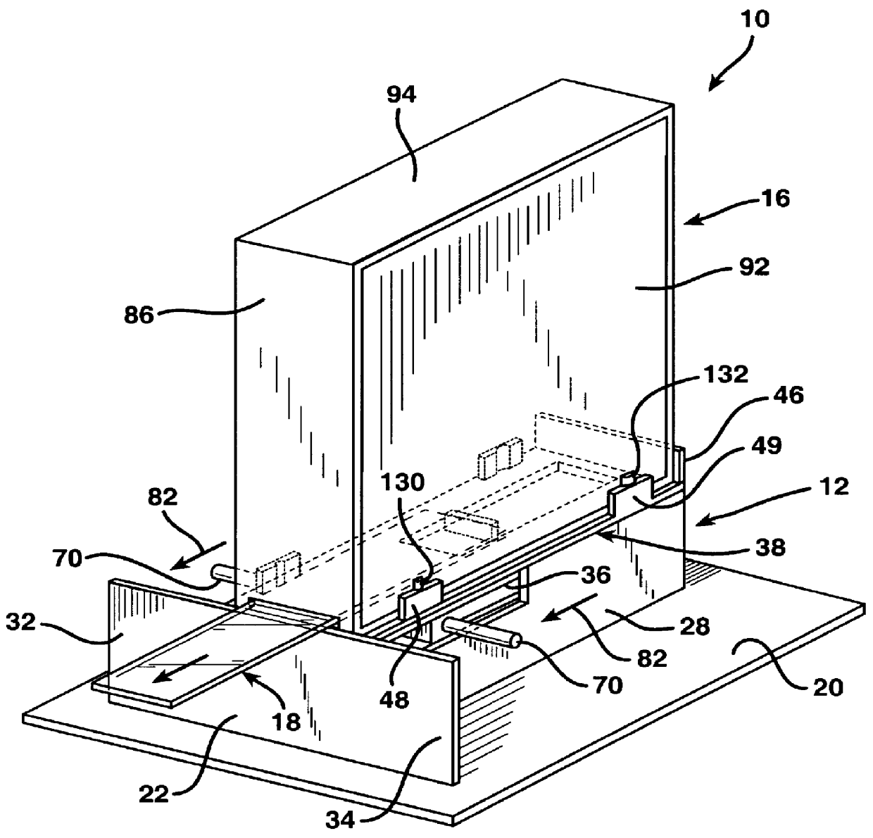
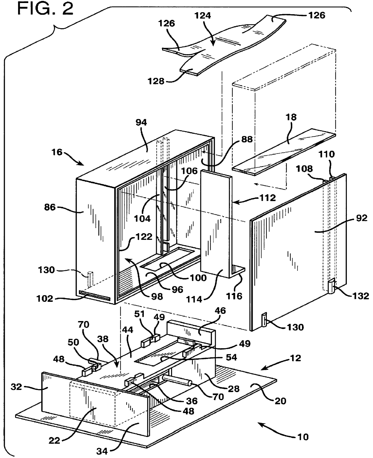
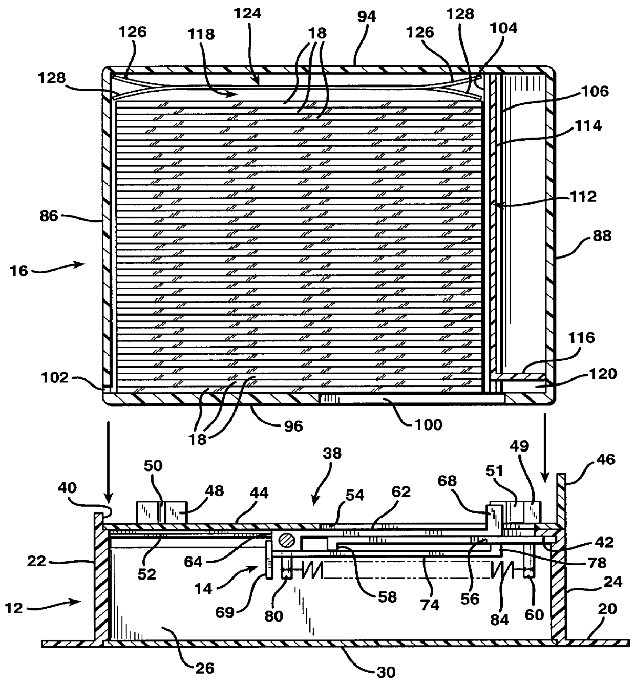
FIG. 1 illustrates a microscope slide dispenser assembly indicated generally at 10. The slide dispenser 10 is comprised of a hollow dispenser base 12, a slide carrier 14 mounted in the base 12 and best depicted in FIGS. 2, 3, 4, and 5, a disposable slide case 16 mounted atop the base 12, and a plurality of flat, microscope slides 18, best depicted in FIGS. 2, 3, 4, and 5.

The hollow dispenser base 12 is a molded plastic structure formed with a flat floor 20 about four and a half inches in length, about three and a half inches in width, and about one-sixteenth of an inch in thickness. The floor 20 has a central, rectangular opening therein about three and nine-sixteenths inches in length and about one and one-quarter inches in width. This opening is surrounded by upright, rectangular shaped base sides 22, 24, 26, and 28. The base sides 22, 24, 26, and 28 define a cavity therewithin shaped in the form of a rectangular prism.

The lower edges of the base sides 22, 24, 26, and 28 overhang ...


PUM

PropertyMeasurementUnit
Thicknessaaaaaaaaaa
Dimensionaaaaaaaaaa
Levelaaaaaaaaaa

Abstract

A microscope slide dispenser is formed with a slide case dispensing attachment having a slide dispensing mechanism and a disposable, plastic slide case that is removably coupled to the dispensing attachment. Positioning members on the dispensing attachment interact with corresponding members on the case to properly position the slide relative to a seating platform or slide case seat. A slide carrier has a finger that projects outwardly from the dispensing attachment and toward the slide case to engage the rear edge of the closest of a plurality of microscope slides stacked within the case. The case is provided with a carrier finger opening and a slide dispensing slot. Operation of the dispensing mechanism engages the carrier finger behind the slide closest to the end wall at which the dispensing attachment is located. The carrier finger pushes the microscope slide closest to the end wall at which the dispensing attachment is located out of the slide case through the slide dispensing slot. The carrier may be spring-biased so that the slide-engaging finger returns to a slide-engaging position behind the next slide, which moves into place once the slide aligned with the slide ejection slot has been ejected. Once all slides have been ejected from the case, the case is discarded.

Description


Claims


Application Information

Patent Timeline
Owner MENES CESAR
Why Eureka
Try Eureka