ATM switch capable of routing IP packet

a technology of atm switches and packet routing, applied in the field of atm switches, can solve the problems of two kinds of facilities, atm routers and atm switches, and the inability to improve the packet transmission capability of the network,

Inactive Publication Date: 2000-11-14
NEC CORP
View PDF14 Cites 55 Cited by
  • Summary
  • Abstract
  • Description
  • Claims
  • Application Information

AI Technical Summary

Problems solved by technology

A first disadvantage of the Prior Art is that two kinds of facilities, ATM routers and ATM switches, are required for constructing an ATM network.
A second disadvantage of the Prior Art is that the packet transmission

Method used


Image

  • ATM switch capable of routing IP packet
  • ATM switch capable of routing IP packet
  • ATM switch capable of routing IP packet

Examples


first embodiment

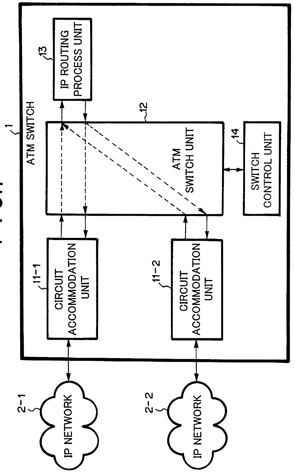
An example of the first embodiment will be explained with reference to FIG. 1.

In FIG. 1, ATM switch 1 is connected with IP network 2-1 and another IP network 2-2 through ATM circuits.

ATM switch 1 comprises circuit accommodation units 11-1 through 11-2, ATM switch unit 12, IP routing process unit 13 and switch control unit 14. IP networks 2-1 and 2-2 are connected with circuit accommodation units 11-1 and 11-2 in ATM router 1, respectively.

Circuit accommodation units 11-1 and 11-2 are connected with ATM switch unit 12, which is controlled by switch control unit 14. ATM switch unit 12 is further connected with IP routing process unit 13.

Although only two IP networks are connected in this example, three or more IP networks can readily be connected.

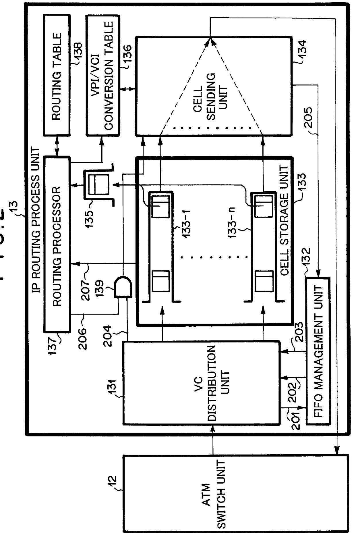
FIG. 2 is a block diagram showing IP routing process unit 13 in detail.

VC distribution unit 131 receives the ATM cells transmitted from ATM switch unit 12 and transfers them to cell storage unit 133. Cell storage unit 133 contains FIFOs 133-1...

second embodiment

A Second Embodiment

A configuration of an ATM switch according to the second embodiment is shown in FIG. 4.

While ATM switch 1 according to the first embodiment shown in FIG. 1 includes one IP routing process unit 13, ATM switch 3 according to the second embodiment shown in FIG. 4 includes a plurality of IP routing process units 13-1 to 13-n.

In accordance with a setting in switch control unit 14, ATM switch unit 12 transfers an ATM cell, which is received at circuit accommodation units 11-1 to 11-m from IP networks 2-1 to 2-m, to any one of IP routing process units 13-1 to 13-n. While only one routing process unit 13 performs the routing process according to the first embodiment, the plurality of IP routing process units 13-1 to 13-n can perform the routing processes according to this embodiment.

Each of circuit accommodation units 11-1 to 11-m is variably connected with any one of IP routing process units 13-1 to 13-n in accordance with the setting by switch control unit 14. For examp...

third embodiment

A Third Embodiment

A connection topology among ATM switches according to the third embodiment is shown in FIG. 5.

While IP networks are connected with a single ATM switch according to the first embodiment, they are connected with a plurality of ATM switches according to this embodiment. In FIG. 5, ATM switches 1-1 and 1-2 are the ATM switches according to the first or second embodiment which include the IP routing process unit. Accordingly, other ATM switches 1-3, 1-4, 1-5 and 1-6 are not required to include the IP routing process unit. In comparison with this embodiment, according to the conventional ATM network, because ATM switches having the routing function are not arranged at the locations of ATM switches 1-1 and 1-2, it is necessary to connect ATM routers to the network.

As explained above, according to the present invention, the following effects are achieved.

A first effect is as follows: Addition of IP routing process unit 13 in FIG. 1 to a conventional ATM switch results in t...


PUM


Abstract

Disclosed is an ATM switch which comprises: an ATM switch unit; a switch control unit for controlling the ATM switch unit; one or more circuit accommodation units for connecting the switch with one or more external ATM networks, respectively, and an IP routing process unit for routing IP packets in a form of ATM cells. In the ATM switch, the IP routing process unit may comprise: a cell storage unit having a plurality of memories; a distributing means for distributing the ATM cells received from the ATM switch unit to the plurality of memories while grouping the ATM cells into each of the plurality of memories in accordance with an IP packet to which each of the ATM cells belongs; sending means for sending all the ATM cells belonging to an identical IP packet when the all the ATM cells belonging to the identical IP packet have been stored in respective one of the plurality of memories; and means for converting VPI/VCI (Virtual Path Identifier/ Virtual Channel Identifier) of the all the ATM cells belonging to the identical IP packet.

Description

1. Field of the InventionThe present invention relates to an ATM switch for use in an ATM network and more particularly, to an ATM switch having a function of routing an IP packet.2. Description of the Related ArtATM router is the general name given to IP (Internet Protocol) routers having one or more ports for accommodating ATM circuits. The port herein explained means an interface which can connect physical circuits such as Ethernet, FDDI and ATM.In case of a router which has only an Ethernet interface defined by an internet standard, IEEE 802.3, an incoming packet from a certain interface is generally output to another interface in accordance with a routing table present within the router.In the ATM circuits, there is a concept of a virtual circuit (hereinafter, referred to as "VC") which can accommodate a plurality of circuits bundled in one physical circuit. Insome ATM routes, the same port receives a packet and transmits the same packet which is subjected to a routing process....

Claims


Application Information

Patent Timeline
IPC IPC(8): H04M11/00H04Q3/00
CPCH04M11/002
Inventor HONDA, MASAHIKOYAMASHITA, MIKIHARU
Owner NEC CORP
Why Eureka
Try Eureka