Switching cabinet with a rack

a technology of switching cabinet and rack, which is applied in the direction of cabinets, substation/switching arrangement details, applications, etc., can solve the problem of correspondingly increasing the cos

Inactive Publication Date: 2000-12-26
RITTALWERK RUDOLF LOH GMBH & CO KG
View PDF9 Cites 13 Cited by
  • Summary
  • Abstract
  • Description
  • Claims
  • Application Information

AI Technical Summary

Problems solved by technology

Now this corner connection requires an additional part, which requires a correspondingly greater expense.

Method used


Image

  • Switching cabinet with a rack
  • Switching cabinet with a rack

Examples


Embodiment Construction

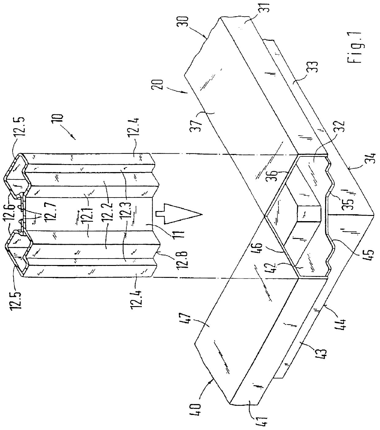
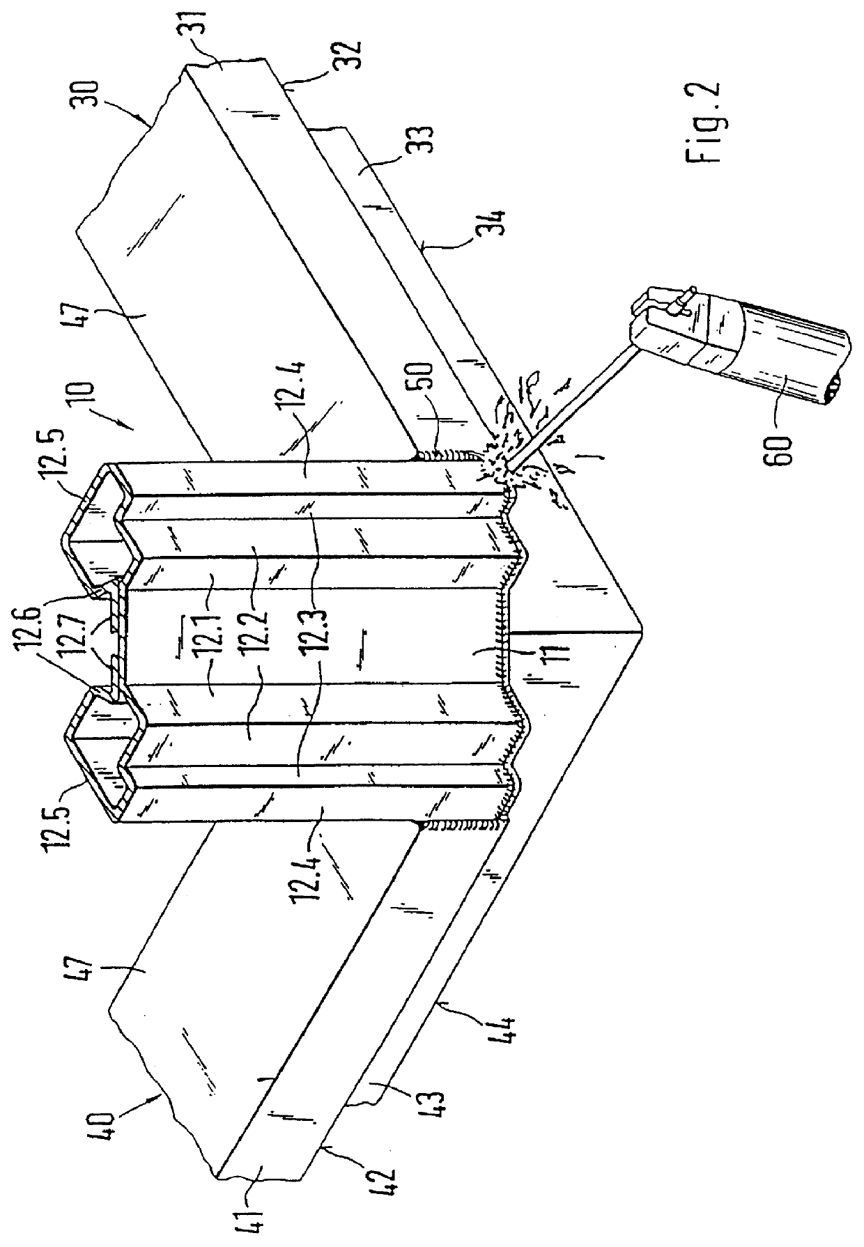
FIG. 1 shows a base 20 which comprises length and depth struts 30, 40. The length and depth struts 30, 40 have the same cross-sectional geometry. The entire base 20 comprises two length and two depth struts 30, 40, which are each aligned parallel to each other. To produce the base 20, a single stamped-flexible part is used, so that the individual length and depth struts 30, 40 are joined together as a single piece. The length and depth struts 30, 40 have a horizontal cover part 37, 47, to which a contact web 31, 41 angled downward by 90.degree. is attached.

The contact web 31, 41 is used to contact a side wall or a cabinet door, for example. A sealing element can be installed between the side wall element or the cabinet door and the contact web 31, 41 to provide the seal. From the contact web 31, 41 there is a horizontal web 32, 42 bent back at a right angle. The horizontal web 32, 42 extends into the downward-directed wall 33, 43. An edge of the wall element or of the cabinet door c...


PUM


Abstract

PCT No. PCT/EP97/06154 Sec. 371 Date May 14, 1999 Sec. 102(e) Date May 14, 1999 PCT Filed Nov. 6, 1997 PCT Pub. No. WO98/23010 PCT Pub. Date May 28, 1998A switching cabinet with a rack having a base made of length and depth struts with connected vertical frame pieces. The vertical frame pieces are inserted into a cavity formed by the ends of the length and depth struts and are welded with the base to form a corner connector. It is possible to create a switching cabinet with a simple corner connector mounted on the rack. It is also possible to achieve precise alignment of the vertical frame pieces by providing them with centering pieces which are aligned with stops of the length and depth struts.

Description

1. Field of the InventionThis invention relates to a switching cabinet with a rack, having a base made of length and depth struts with connected vertical frame pieces, where the vertical frame pieces are inserted into a cavity formed by the ends of the length and depth struts and are welded with the base to form a corner connector.2. Description of Prior ArtA switching cabinet of this kind is known, for example, from German Patent Reference DE 19 04 558. In switching cabinets of this kind a separate corner connector is omitted, so that the single vertical frame leg and length or depth struts are welded directly to each other. The length and the depth struts are designed as angled profiles. The depth strut is butt welded by its planar front side to a leg of the length strut.The vertical frame leg designed as angle profile and likewise having two legs can then be tied to the formed base. In this case, one of the legs has a front release. Thus, of the second leg there remains a front g...

Claims


Application Information

Patent Timeline
Patent Type & Authority Patents(United States)
IPC IPC(8): H02B1/30H02B1/00H02B1/01
CPCH02B1/01H02B1/301H02B1/014
Inventor BENNER, ROLFKOHLER, MARTINAMUNCH, UDOREUTER, WOLFGANG
Owner RITTALWERK RUDOLF LOH GMBH & CO KG
Why Eureka
Try Eureka