Moving picture encoding apparatus and method

a picture and encoding technology, applied in the field of moving picture encoding apparatus and method, can solve the problems of deteriorating picture quality, limiting the number of bits generated in the first half, and affecting the quality of the imag

Inactive Publication Date: 2001-01-09
PANASONIC CORP
View PDF3 Cites 44 Cited by
  • Summary
  • Abstract
  • Description
  • Claims
  • Application Information

AI Technical Summary

Benefits of technology

It is therefore an object of the present invention to provide a moving picture encoding apparatus and method capable of distributing bits appropriately depending on the difficulty in encoding the moving picture.
It is yet another object of the present invention to provide a moving picture encoding apparatus and method for determining target bits to be generated to absorb the error between the target number of generated bits to be generated in one image segment composed of a plurality of pictures, such as a GOP, and the number of actually generated bits, gradually over a plurality of image segment groups.
It is a further object of the present invention to provide a moving picture encoding apparatus and method for controlling the target quantity of generated bits so that the target quantity of generated bits does not change abruptly in adjacent picture segment groups.
It is a further object of the present invention to provide a moving picture encoding apparatus and method capable of controlling an optimum quantizing width on the basis of the target number of generated bits to be generated in one image segment group.

Problems solved by technology

As a result, the picture quality may deteriorate.
Or, if the actual number of generated bits increases considerably from the target number of generated bits in a certain GOP, the quantizing parameter is controlled so that the target number of generated bits in next GOP may absorb this error, and the picture quality in that GOP may likewise deteriorate.
Furthermore, if complicated images are concentrated in the first half of a picture, the number of bits generated in the first half is limited, and bits are not ideally assigned.
However, it is difficult to provide such encoding in real time.

Method used


Image

  • Moving picture encoding apparatus and method
  • Moving picture encoding apparatus and method
  • Moving picture encoding apparatus and method

Examples


second embodiment

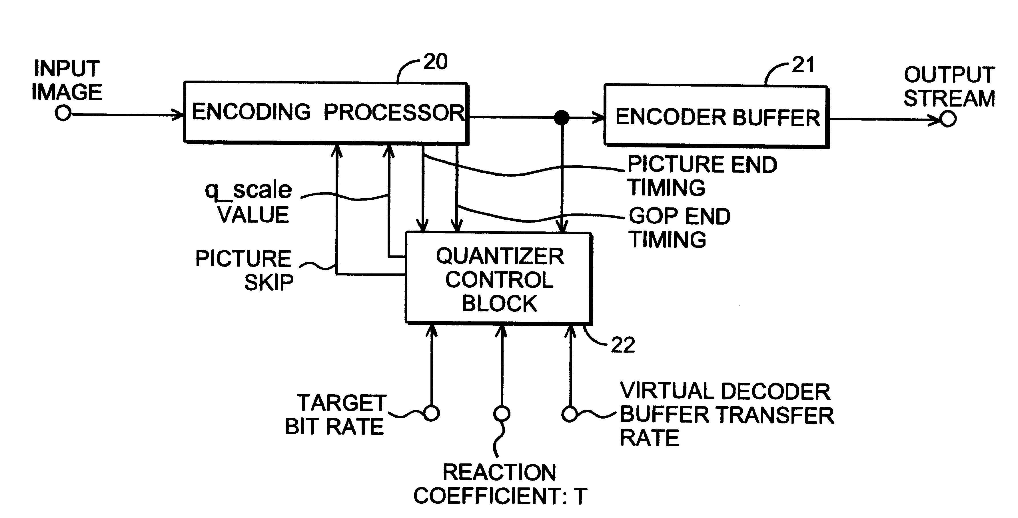
the present invention is described below. FIG. 13 is a block diagram showing a second embodiment of the invention, in which an input signal is supplied to an encoding processor 20. The encoding processor 20 encodes each macro block into a signal conforming to MEPG2 according to the value of quantizing width q_scale indicated by a quantizer control block 22, and supplies the encoded signal to an encoder buffer 21 and the quantizer control block 22. The encoding processor 20 also supplies the received GOP end timing signal and picture end timing signal to the quantizer control block 22. The quantizer control block 22 determines the quantizing width q_scale from the target bit rate, reaction coefficient T, and encoded data and timing signal supplied from the encoding processor 20, and supplies the quantizing width q_scale to the encoding processor 20, and controls the number of generated bits and picture quality.

FIG. 14 is a block diagram showing an example of the quantizer control blo...

first embodiment

FIGS. 18a-c are graphs schematically showing changes in the number of bits generated in relation to the complexity of an input image and the picture quality. FIG. 18(a) shows the changes of complexity occurring in a sufficiently short time for the reaction coefficient T and changes of the number of generated bits and picture is quality according to the That is, if the complexity of the image changes in a relatively short time interval, the number of generated bits is assigned depending on the complexity of encoding the image, and it is understood that the picture quality can be kept almost constant.

On the other hand, as shown in FIG. 18(b), when encoding of an input image is extremely difficult and such a signal is supplied for a relatively long time, according to the assigning method of the target number of bits of the first embodiment, the number of bits is generated depending on the complexity of the input image, and later, the bit generation amount decreases exponentially with ...


PUM


Abstract

An MPEG2 conforming encoding apparatus and method wherein a control unit adjusts a target number of bits depending on the result of dividing by at least 2 the error between a target number of bits corresponding to the target bit rate and the number of generated bits required for encoding an immediately preceding image segment group, and controls a quantizing parameter for encoding the image segment group in accordance with the adjusted target number of bits.

Description

The present invention relates to a method and apparatus for digital compression encoding of images, such as video signals, and more particularly to an apparatus and method for controlling the quantizing width when encoding and / or controlling the number of bits generated.An international standard for compressing image signals and converting same into a digital code is known as ISO / IEC 13818-2, also known as MPEG2. A typical method of digital encoding image signals conforming to that format is shown in Test Model 3 of ISO-IEC / JTC / SC29 / WG11 No. 328. FIG. 1 of the present drawings is a block diagram of a typical MPEG2 video encoding apparatus. This MPEG2 video encoding apparatus comprises a frame converter 101 for shuffling input video signal into encoding sequence, a block converter 102 for converting picture data into encoding units called macro blocks, a subtractor 103 for determining the difference between an input macro block and a predicted value with respect to its image data, a ...

Claims


Application Information

Patent Timeline
Patent Type & Authority Patents(United States)
IPC IPC(8): G06T9/00H04N7/30H04N7/26H04N7/50
CPCH04N19/172H04N19/149H04N19/15H04N19/61H04N19/60H04N19/126H04N19/132H04N19/14H04N19/142H04N19/177H04N19/179H04N19/87H04N19/13H04N19/91H04N19/146H04N19/152H04N19/124
Inventor KATTA, NOBORUNAKAMURA, KAZUHIKO
Owner PANASONIC CORP
Why Eureka
Try Eureka