Crease-free combination hanger

Inactive Publication Date: 2001-01-16
ACCESSORY CORP THE
View PDF8 Cites 62 Cited by
  • Summary
  • Abstract
  • Description
  • Claims
  • Application Information

AI Technical Summary

Problems solved by technology

These clamp-type garment hangers which utilize teeth, often sharp or otherwise pointed, suffer from the drawback of introducing unwanted creases, marks, holes, projections or disfigurations to the garment.
Where the garment is especially delicate, these hangers heretofore in use can be particularly harmful to the garment.
This attaching process is also expensive and introduces undesirable complexities into the manufacturing process.
Moreover, the material from which these gripping pads have been made have an unwanted tendency to become sticky when subject to increased temperatures.
This can become particularly harmful to garments when hangers of

Method used


Image

  • Crease-free combination hanger
  • Crease-free combination hanger
  • Crease-free combination hanger

Examples


Embodiment Construction

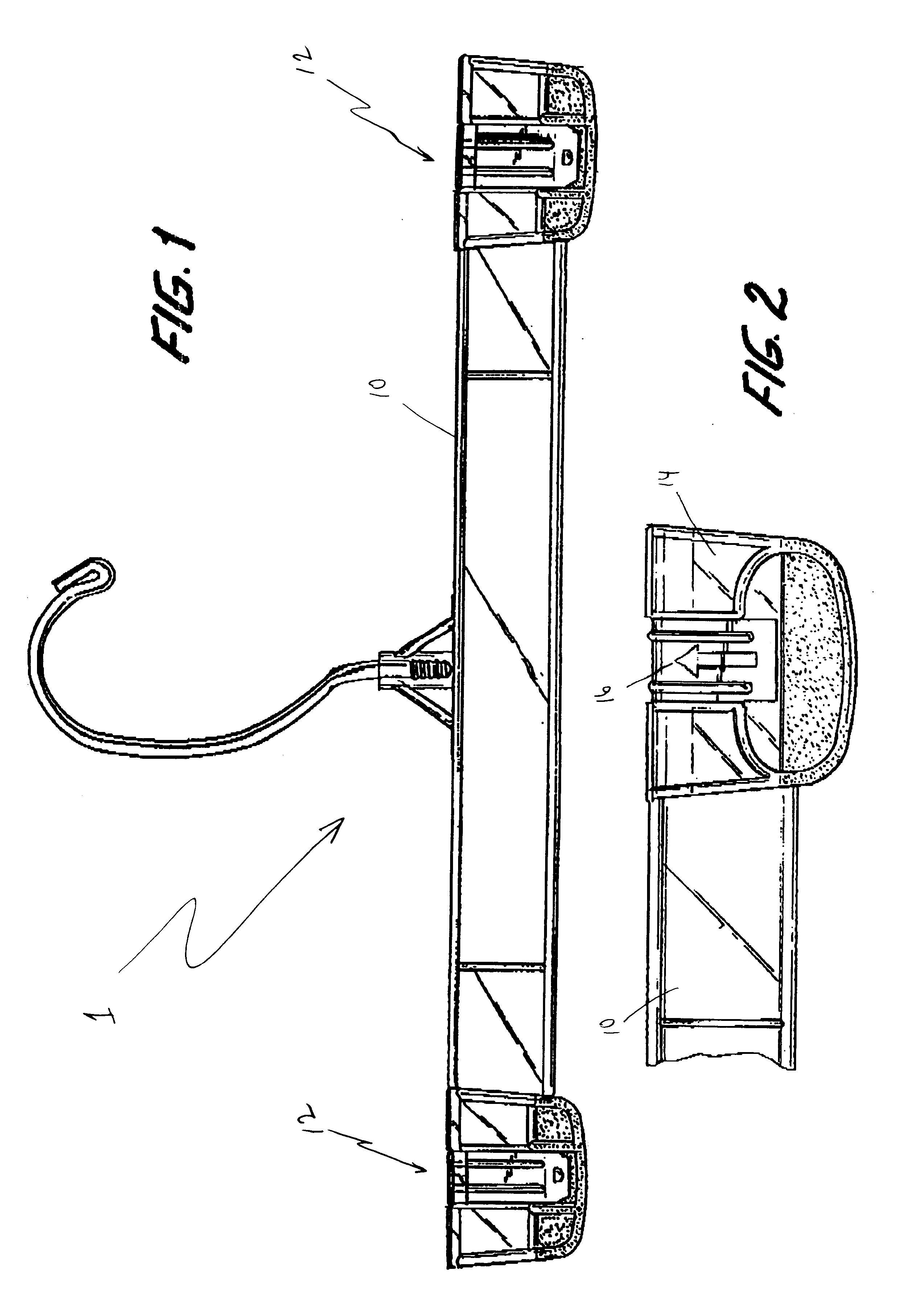
Referring now to FIG. 1, a clamp-type garment hanger 1 in accordance with the present invention is shown. Clamp-type garment hanger 1 includes a partial loop or hook member (not numbered), which may be formed from plastic or metal wire or any other appropriate material. The partial loop or hook member may be secured via threads to body 10, as shown, or may be integrally formed from the same material as body 10, or may be connected to the body in any other manner.

Clamp-type garment hanger has body 10, and has at its ends clamps generally indicated as 12. Clamps 12 are formed from the same material as body 10, and are also molded or otherwise formed integrally with, and from the same materials as, body 10. It is noted that, although shown with clamp 12 at each of its ends, the present invention recognizes that only one clamp 12 may be used.

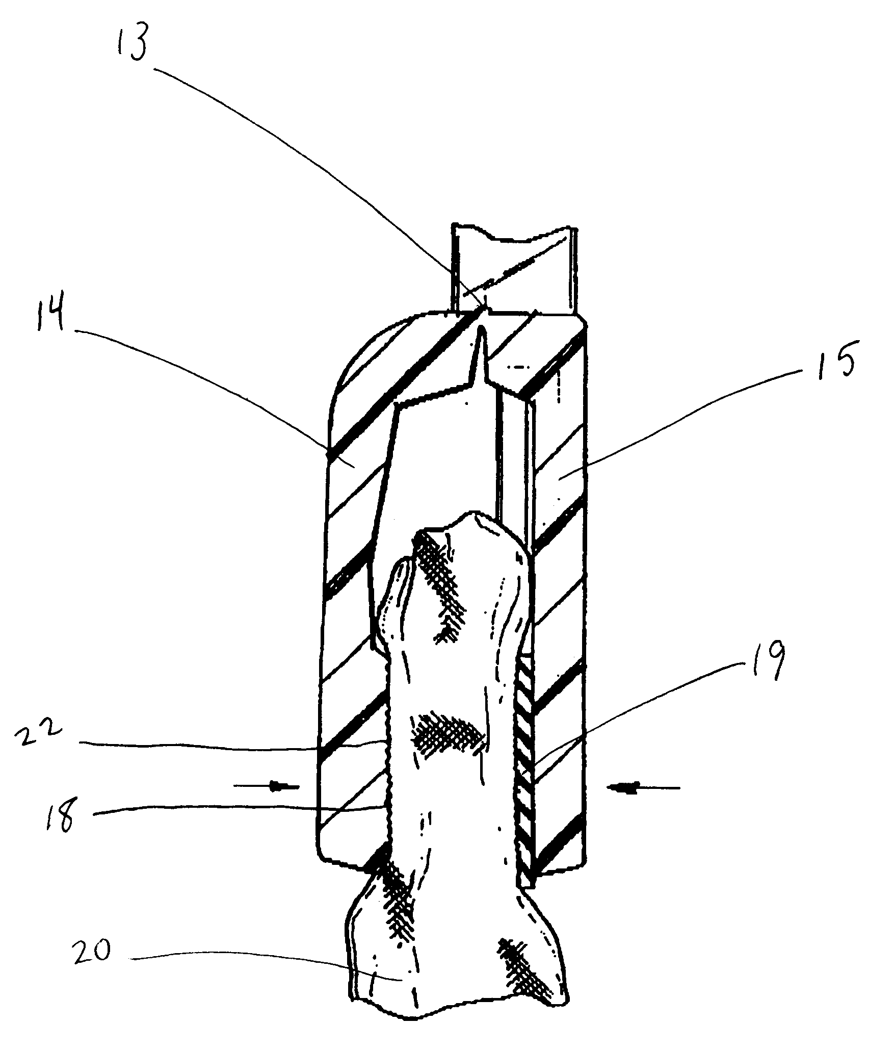
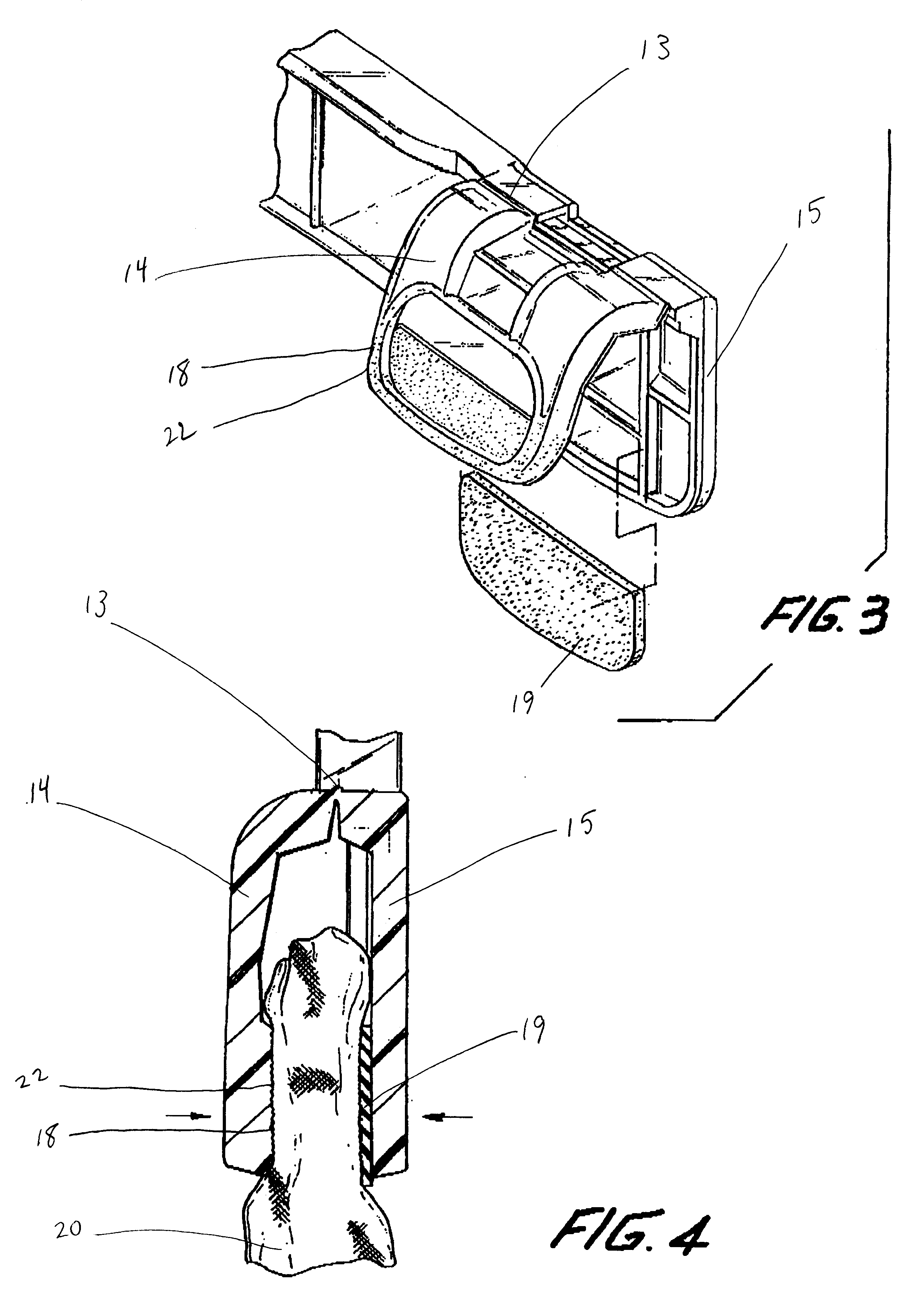
As best shown in FIGS. 3 and 4, clamp 12 has along its upper edge a hinge 13. Clamp 12 includes a front jaw member 14 and a rear jaw member 15. One...


PUM


Abstract

A clamp-type garment hanger defined by a pair of opposed jaw members between which a garment is hung. The opposed jaw members have gripping members and opposed gripping surfaces. The gripping members, opposed gripping surfaces and jaw members of one jaw member are formed from the same material, which may include either polystyrene, polypropylene, polyethylene, styrene-butadiene copolymers and blends, or polycarbonates. The other jaw member has bonded thereto an elastomer material for gripping the garment. To increase the coefficient of friction of the opposed gripping surfaces, the surfaces may be treated by engraving, acid etching, electrical discharge machining, vapor honing, or sandblasting.

Description

1. Field of the InventionThe present invention relates to hangers. More specifically, the present invention relates to a clamping-type garment hanger which prevents unwanted creases or imprints, and which is more economical to manufacture than clamping-type garment hangers heretofore in use.2. Discussion of the Related ArtClamping-type garment hangers have heretofore been provided for the suspension or hanging of articles such as pants, skirts, etc. Such hangers include at least one clamp typically defined by a pair of opposed clamp or jaw members between which the article is placed. Provision is made for biasing the members to create the clamping force necessary to retain the article between the inner surfaces of the jaw members. To further retain the article between the inner surfaces of the members, the clamp or jaw members have heretofore also included on its inner surfaces teeth elements or a friction surface separately attached to the inner surfaces of the clamp or jaw members...

Claims


Application Information

Patent Timeline
IPC IPC(8): A47G25/00A47G25/48
CPCA47G25/483Y10T24/44444
Inventor COHEN, BERNARD J.
Owner ACCESSORY CORP THE
Why Eureka
Try Eureka