
Chair with leg reinforcement bar

Inactive Publication Date: 2001-01-16
MICHIGAN TUBE SWAGERS & FABTORS
View PDF32 Cites 34 Cited by
  • Summary
  • Abstract
  • Description
  • Claims
  • Application Information

AI Technical Summary

Problems solved by technology

Generally the inclusion of a bar extending between the legs to support the seat at the rear of the chair interferes with the stacking of the chairs and thus substantially diminishes one of the important advantages of such chairs.

Method used


Image

  • Chair with leg reinforcement bar
  • Chair with leg reinforcement bar

Examples


Embodiment Construction

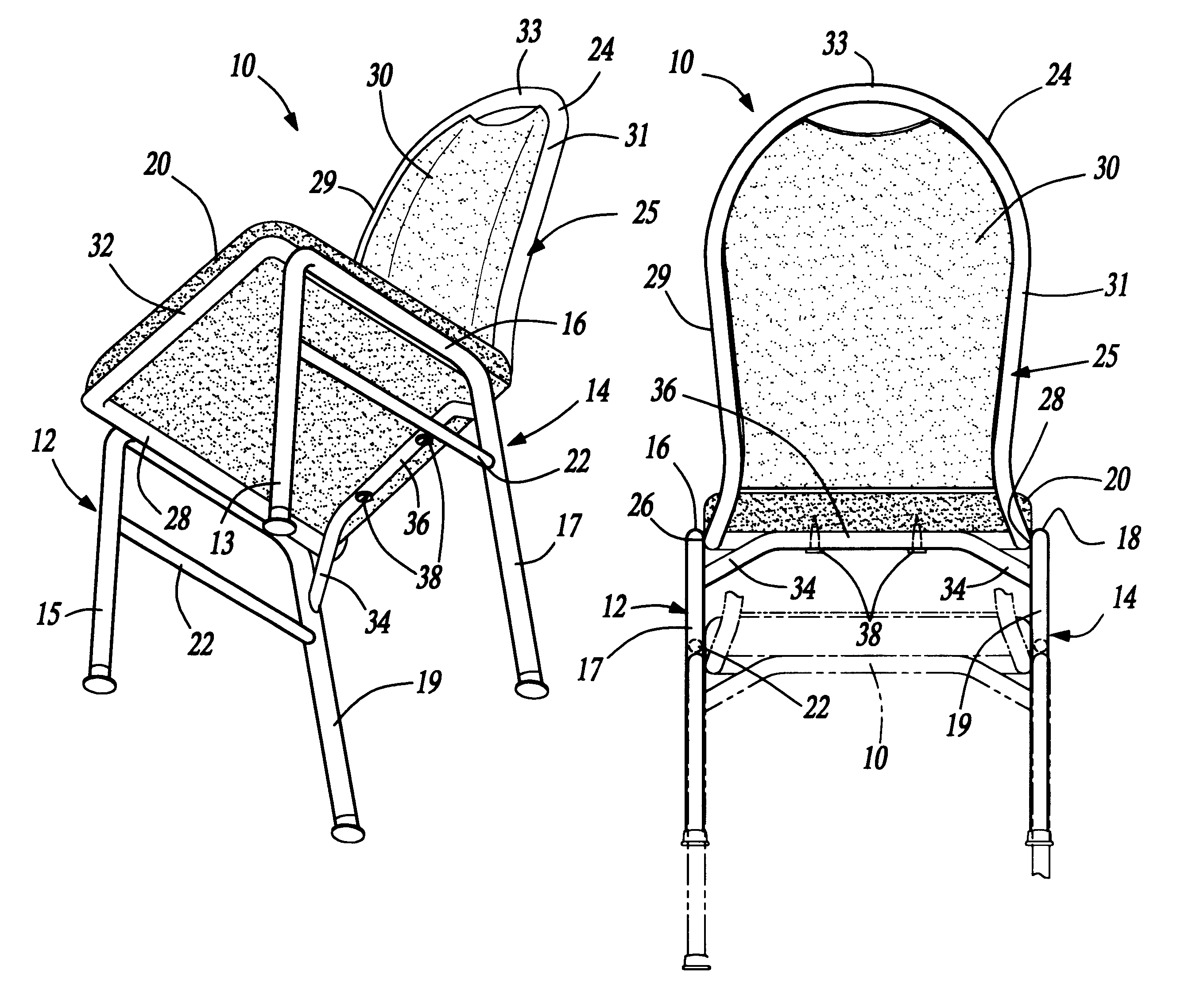
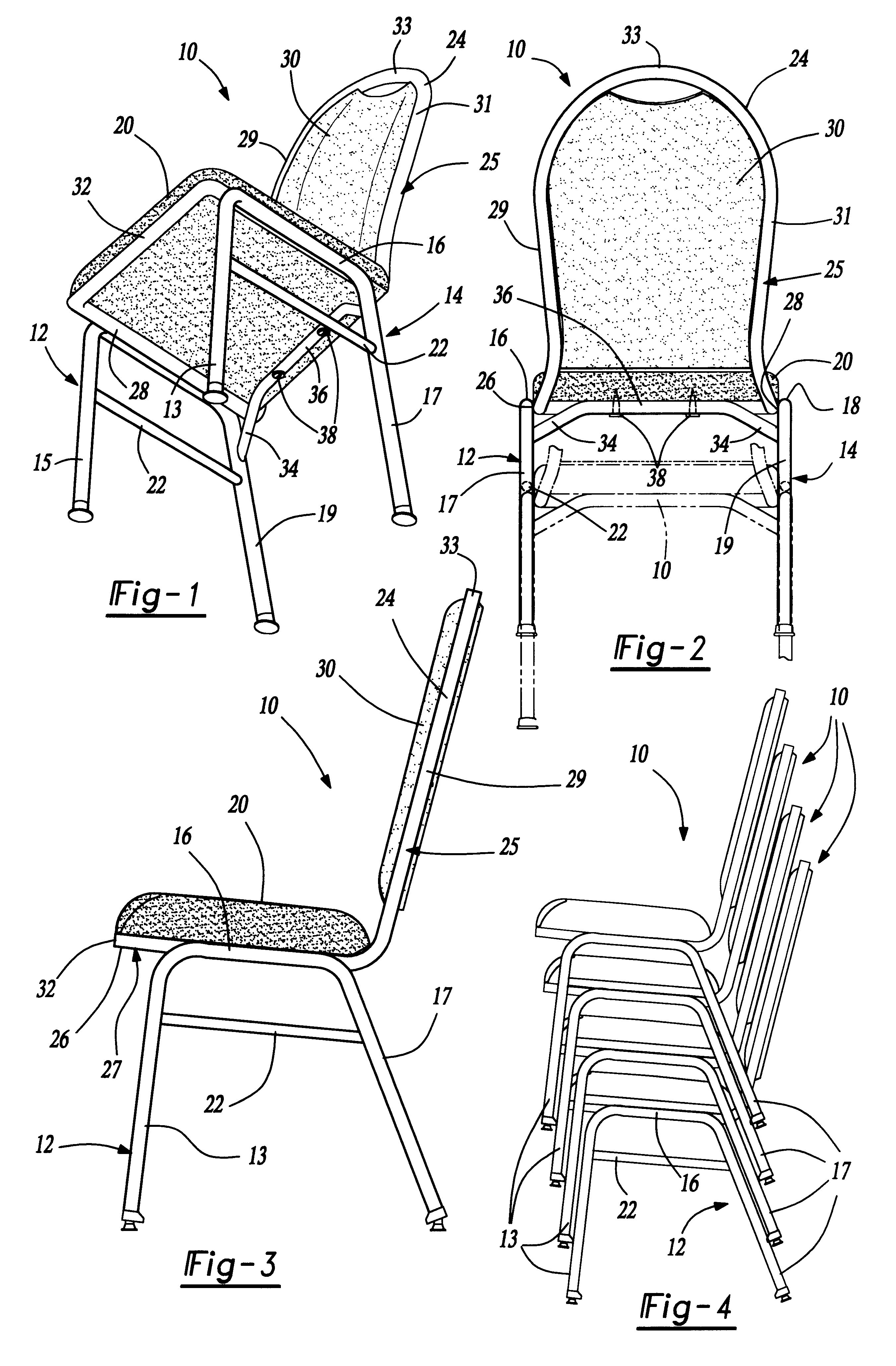
With reference to the FIGS. 1, 2 and 3, a preferred embodiment of the present invention is illustrated and comprises a chair generally indicated at 10 and having a pair of opposed, substantially U-shaped legs or leg members 12 and 14. As can best be seen in FIG. 1 the legs 12 and 14 form an inverted U shape with the upper, substantially horizontally extending, portions 16 and 18 respectively of the legs 12 and 14. Still referring to FIG. 1, upper, substantially horizontally extending portions 22 extend between the front and rear leg portions 13, 15 and 17, 19 respectively of the U-shaped legs 12 and 14 respectively on each side of the chair 10 to provide support for the legs 12 and 14.

Still referring to FIGS. 1-3, a chair back frame member 24 is provided with horizontally extending side members 26, 28 respectively joined by welding or the like to the horizontally extending portions 16 and 18 of the legs 12 and 14. A substantially vertically extending section 25 of the frame member 2...


PUM


Abstract

A chair is formed to permit stacking when not in use and includes a pair of inverted substantially U-shaped leos joined together by a seat cushion and a back cushion supporting frame member. A leg reinforcement bar ties the U-shaped legs together and has an intermediate upwardly formed portion which engages the seat cushion along a line of contact to support the rear of the seat cushion.

Description

The present invention relates to chairs and more particularly to a chair having a leg reinforcement bar which supports the seat of the chair while reinforcing the legs of the chair and still permitting a number of chairs to be snugly nested in a stacking relationship.DESCRIPTION OF THE PRIOR ARTChairs with legs in the form of an inverted U shape and in which the seat of the chair is supported by upper transversely extending portions of the U-shaped legs have been heretofore provided. In addition to the simplicity in construction of such chairs the main advantage is that they can be stacked one on top the other and they nest together to minimize the necessary storage room.Generally the inclusion of a bar extending between the legs to support the seat at the rear of the chair interferes with the stacking of the chairs and thus substantially diminishes one of the important advantages of such chairs.U.S. Pat. No. 2,981,319 to Close discloses a chair having a leg reinforcement bar which ...

Claims


Application Information

Patent Timeline
Patent Type & Authority Patents(United States)
IPC IPC(8): A47C3/04A47C3/00
CPCA47C3/04
Inventor SWY, PHILIP P.
Owner MICHIGAN TUBE SWAGERS & FABTORS
Learn More