Forward sliding reclining chair

a reclining chair and forward sliding technology, applied in the direction of chairs, movable seats, transportation and packaging, etc., can solve the problems of limiting or eliminating the effectiveness of lumbar support, not providing adequate contours and/or bends to support users in the above described reclined body position, and common office chair recline mechanisms may not be fully accommodating for certain users.

Inactive Publication Date: 2014-04-17
HAWORTH SPA
View PDF6 Cites 67 Cited by
  • Summary
  • Abstract
  • Description
  • Claims
  • Application Information

AI Technical Summary

Benefits of technology

[0012]The above noted movement of the chair of the present invention provides good back and upper leg support for a user from full upright to an extreme reclined position. More particularly, the progressive bending of the back support in the area just below the user's shoulders maintains the user's head and shoulders substantially upright while the user moves from fully upright to a reclined posture, and the progressive bending of the back support in the area just below the user's shoulders maintains support to the user's lower back while the user moves from fully upright to a reclined posture. The bending of the seat portion of the chair relieves pressure from under the user's upper legs as the user moves from fully upright to a fully reclined position.
[0014]In another embodiment, the chair includes a lumbar pressure arm and the backrest includes a lumbar support having a surface for supporting the seated user's lower back area. The lumbar support is mounted on a support arm, and the support arm is pivotally mounted to the backrest. The lumbar pressure arm is mounted to the chair and configured to engage the lumbar support arm as the backrest rotates from the upright position to the reclined position. The rotation of the backrest to the reclining position increases the engagement force of the lumbar support arm on the pressure arm, and consequently moves the lumbar support towards a seated user's lower back. The adjustable lumbar support device can thus move forwardly with respect to the chair backrest as the user moves from fully upright to a reclined posture to maintain engagement with the user's back.
[0015]In yet another embodiment, the movements of the chair can be controlled with electrically powered motion for moving the user from fully upright to intermediate positions or a fully reclined position and returning back to the fully upright position with reduced effort.

Problems solved by technology

However, common office chair recline mechanisms may not be fully accommodating for certain users that prefer to work in a reclined position with the body stretched into a straightened form.
Typical reclining office chairs provide substantially planar seat support and back support surfaces that may adequately support the user when the user sits upright, but they do not provide adequate contours and / or bends that will support a user in the above described reclined body position.
This may limit or eliminate the effectiveness of the lumbar support while increasing the pressure of the buttocks on the seat ledge.
Unfortunately, the user sacrifices proper lower back and upper leg support to achieve this working position.
However, neither the seat nor the backrest of this chair conform to the shaped of a user in the above noted reclined body position.
Also, the upper back of a user in this chair tends to fall away from the user's computer monitor, moving the user's eyes significantly rearward.
Similarly, the upper back of a user in this chair tends to fall away from the user's computer monitor and other objects sitting on the user's worksurface, moving the user's eyes significantly rearward.
However, the seat and backrest do not move forward as backrest reclines, leaving the seat out of position, and the backrest (and any lumbar support) spaced away from the back of a person in the above noted recline position.

Method used


Image

  • Forward sliding reclining chair
  • Forward sliding reclining chair
  • Forward sliding reclining chair

Examples


first embodiment

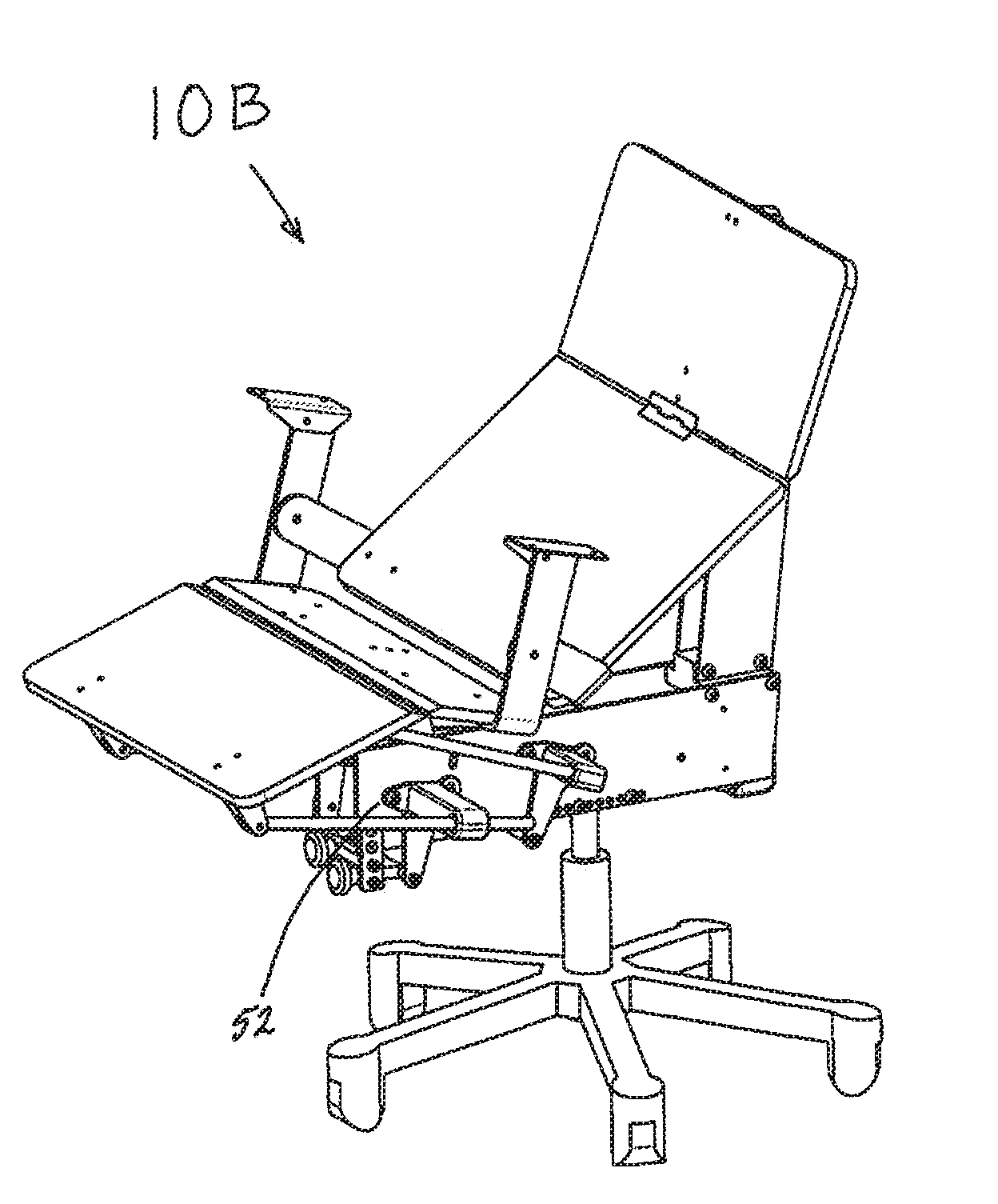
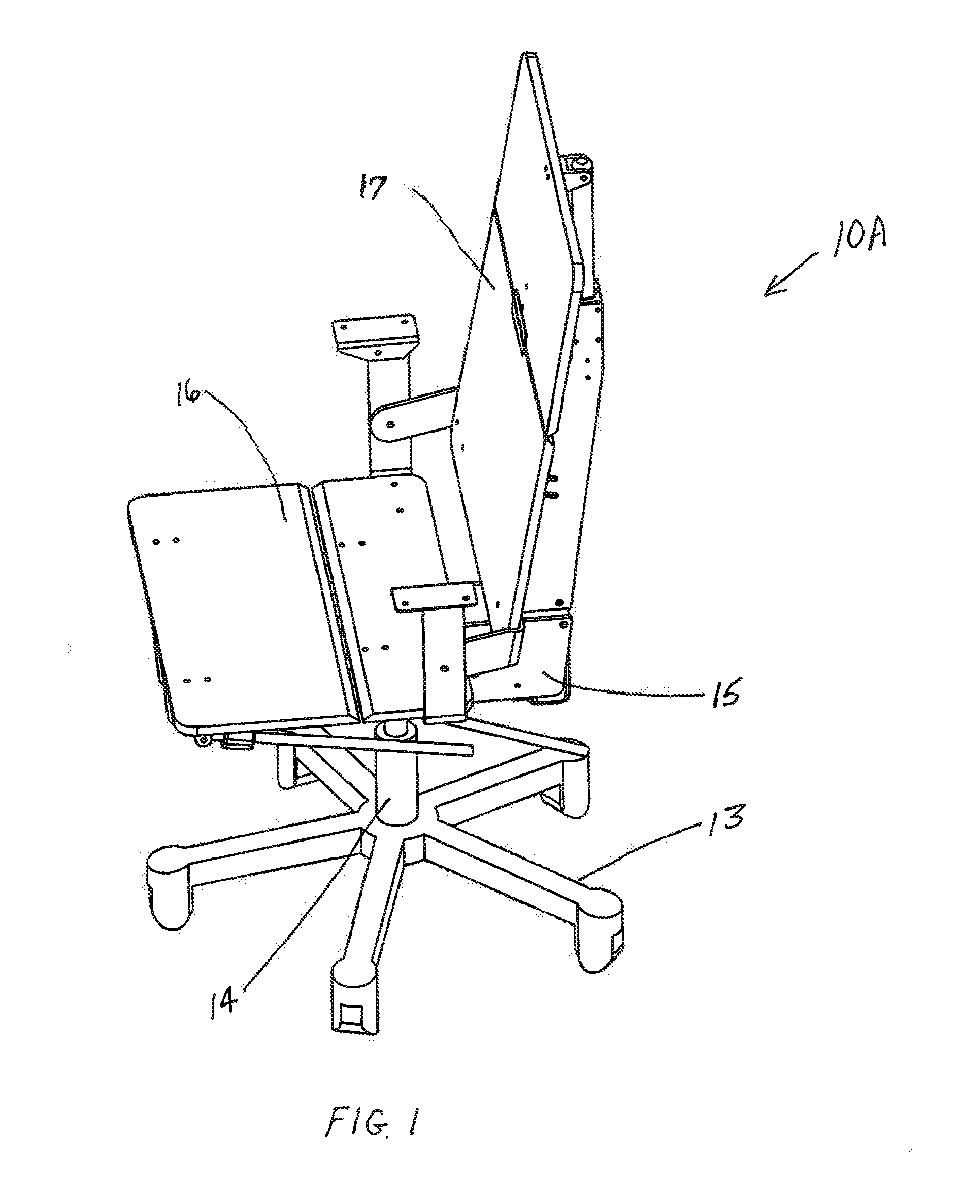
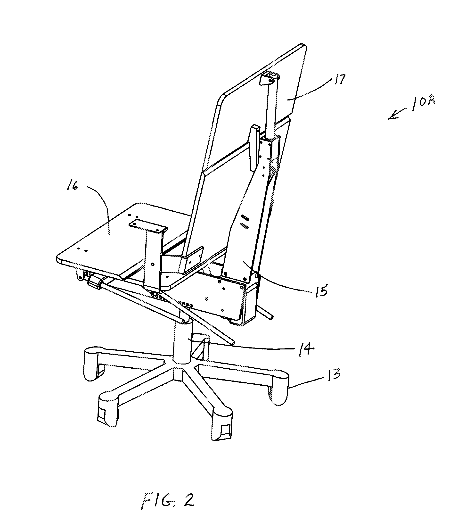
[0079]Referring to FIGS. 1-10, there is illustrated the forward sliding reclining swivel chair 10A (herein-after referred to as the “chair” for convenience) configured with a power driven recline mechanism.

[0080]The chair 10A includes a wheeled base assembly 13 having an upright support post 14 projecting therefrom. The upright support post 14 in turn mounts thereon a guide frame 15 which supports a slidable seat 16 which is pivoted to a reclinable back support 17, for supporting a seated user / occupant. The wheeled base assembly 13 includes a set of swiveling casters 38. Referring to FIG. 6, seat 16 has a front 18 and rear 19 portions that are pivotally connected by hinge 20. Back support 17 has upper 21 and lower 22 portions that are pivotally connected by hinge 23. The lower back support portion 22 is pivotally connected to seat rear portion 19 at pivot pins 24.

[0081]In one embodiment, the upper back portion 21 is pivotally connected near the top thereof to upper guide 25 by pin 2...

seventh embodiment

[0114]FIGS. 49-53 describe the forward sliding reclining swivel chair 10G. The basic structure and motions of chair 10G are nearly identical to chair 10F except that the motions are powered by an electric linear actuator 380 that replaces gas spring 280. Roller guide frame 335 includes all the components of roller guide frame 235 except bracket 275 and ball pivot 274 are replaced by bracket 375 and pivot pin 374. Seat rear portion 327 includes all the components of seat rear portion 227 except bracket 277 and ball pivot 276 are replaced by bracket 377 and pivot pin 376. Linear actuator 380 includes body portion 310 and drive rod 396. Body portion 310 includes motor 394 and screw housing 395. Linear actuator 380 is pivotally attached to bracket 377 at pivot pin 376 near the rearward end 397 of screw housing 395 thereof. Drive rod 396 is pivotally attached to bracket 375 at pivot pin 374 at the forward end thereof. The operation of linear actuator 380 is conventional in that, the shaf...

eighth embodiment

[0116]FIGS. 54-58 describe the forward sliding reclining swivel chair 10H. This embodiment is not motor driven. The recline motions are powered by gravity and the user / occupant while a gas compression spring 480 assists the user / occupant in the return stroke from reclined back to upright.

[0117]Chair 10H includes a wheeled base assembly 13 having an upright support post 14 projecting therefrom which includes a conventional height adjustable gas spring (not shown). Upright support post 14 in turn mounts thereon roller guide frame 435 which supports slidable seat assembly 470 which has pivotally connected thereto reclinable back support 471, for supporting a seated user / occupant.

[0118]The upper face of seat assembly 470 will normally be covered by a layer of foam cushioning and fabric, which is not shown. The wheeled base assembly 13 includes a set of swiveling casters 38. Seat 470 has front 425 and rear 427 portions that are pivotally connected by hinge 426.

[0119]Back support 471 has ...


PUM


Abstract

An office chair includes a seat and a backrest that are pivotally connected together at a pivot axis such that the backrest can pivot with respect to the seat between an upright position and a reclining position. The seat is mounted on a base such that the seat can move with respect to a base, and the seat includes front and rear portions that can pivot with respect to one another. When the backrest is pivoted from the upright position to the reclining position, both of the seat and the pivot axis move forward with respect to said base, and the seat front portion flexes with respect to the seat rear portion such that the angle between said upward faces of said seat front portion and the seat rear portion increases. The backrest may also include an upper portion and a lower portion that can pivot with respect to one another. When the backrest is moved to the recline position, the angle between the forward faces of the upper and lower backrest portions decreases.

Description

FIELD OF THE INVENTION[0001]This invention relates to an improved reclining swiveling task chair of the type used in offices.BACKGROUND OF THE INVENTION[0002]Modern reclining office chairs can be quite comfortable for many people, and, due to advances in recline technology, can be comfortable for users sitting in various positions from upright to reclined. However, common office chair recline mechanisms may not be fully accommodating for certain users that prefer to work in a reclined position with the body stretched into a straightened form. For example, it is common to see a designer or computer programmer in an extremely reclined position where they have slid forward into a position where their buttocks is supported only by the front edge of their chair seat and their back is only supported in the upper back area by the chair backrest support. With their feet on the floor, the seat front edge is serving as a ledge for the user's buttocks to stop them from sliding completely off t...

Claims


Application Information

Patent Timeline
Patent Type & Authority Applications(United States)
IPC IPC(8): A47C1/032A47C1/022A47C7/46
CPCA47C1/032A47C1/022A47C7/46A47C1/03211A47C1/03255A47C1/03294A47C7/024A47C7/14A47C7/38A47C7/405
Inventor WILSON, HAROLD R.
Owner HAWORTH SPA
Why Eureka
Try Eureka