Catalyst unloading device

Inactive Publication Date: 2001-02-06
PHILIP ST
View PDF4 Cites 47 Cited by
  • Summary
  • Abstract
  • Description
  • Claims
  • Application Information

AI Technical Summary

Problems solved by technology

Difficulties have been encountered in removing catalyst, such as granular or particulate catalyst, from the tubes of multi-tube reactors.
The catalyst is prone to becoming lodged within the tubes during reactor operation.
Often, the particulate catalyst may completely block or bridge some or all of the tubes of the reactor due to heat or composition changes during operation, resulting in retarded or blocked movement or flow of the catalyst.
In actual operation, air-motor powered air lance reels have presented several problems.
Because the air-powered reel uses a compressible flui

Method used


Image

  • Catalyst unloading device
  • Catalyst unloading device
  • Catalyst unloading device

Examples


Embodiment Construction

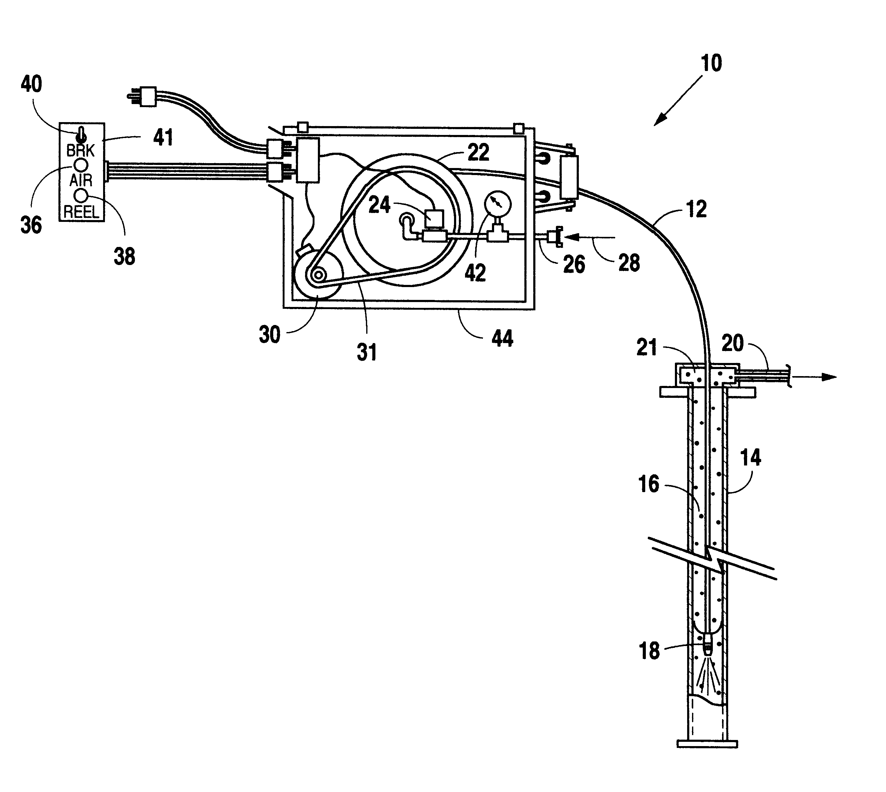
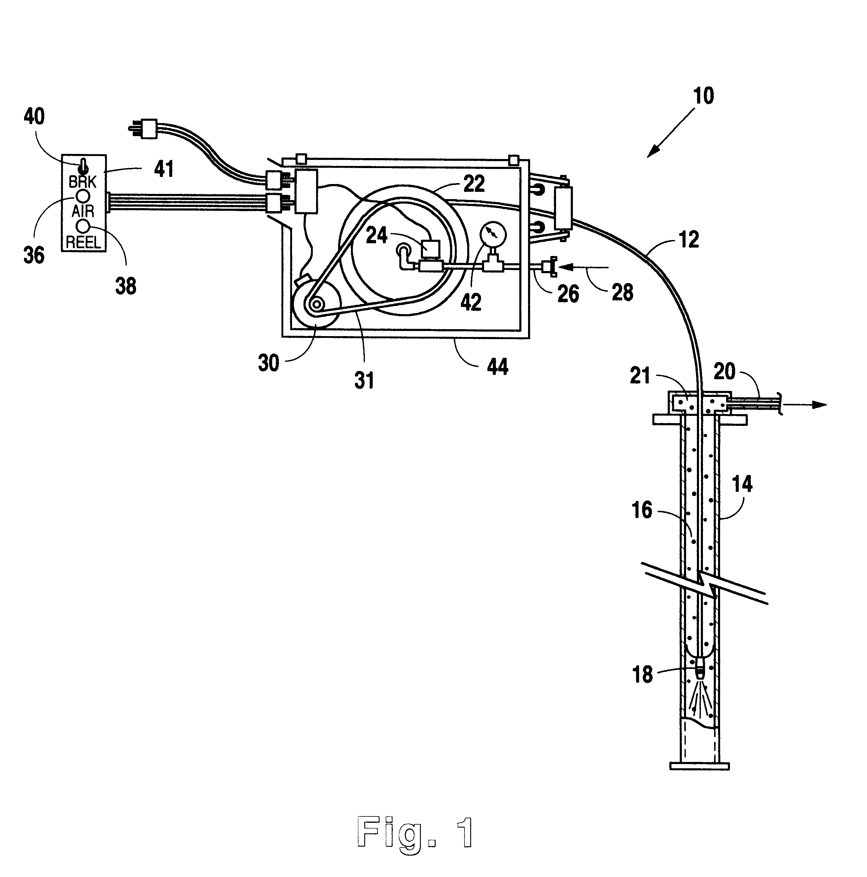
In the preferred embodiment of the present invention, a catalyst unloading device is generally indicated in FIG. 1 by the reference numeral 10. The catalyst unloading device 10 is specifically arranged to control the movement of a flexible, compressed-fluid, conduit, such as an air lance, 12 during insertion into a reactor tube 14, and subsequently upwardly withdraw the air lance 12 from the tube 14. The reactor tube 14 is filled with catalyst 16 that is no longer suitable for use in a reaction process, or for other reasons must be removed from the reactor tube 14. A nozzle 18 is disposed at a distal end of the flexible air lance 12. The preferred nozzle for use is that which is described in U.S. Pat. No. 5,222,533, which is incorporated herein for all purposes. More specifically, when air is used as the compressed fluid, and the air lance 12 is inserted into the reactor tube 14, compressed fluid is discharged through the nozzle 18 and produces a high pressure gas jet to dislodge an...


PUM

PropertyMeasurementUnit
Forceaaaaaaaaaa

Abstract

An electric motor is operatively connected to a reel for selectively storing, paying out, and rewinding an air lance of a device for unloading catalyst from tubular reactors. The electric motor powered reel provides improved on/off control of the air lance mounted on the reel, a braking force during withdrawal of the air lance from the reel, constant speed operation during rotation of the reel, and avoids the problem of lubricant contamination of the catalyst and reactor tubes.

Description

1. Technical FieldThis invention relates generally to a device for unloading catalyst from a tubular reactor, and more particularly to such a device that has an air lance that is mounted on a motor-driven reel.2. Background ArtDifficulties have been encountered in removing catalyst, such as granular or particulate catalyst, from the tubes of multi-tube reactors. The catalyst is prone to becoming lodged within the tubes during reactor operation. Often, the particulate catalyst may completely block or bridge some or all of the tubes of the reactor due to heat or composition changes during operation, resulting in retarded or blocked movement or flow of the catalyst.U.S. Pat. No. 5,228,484, issued Jul. 20, 1993 to Kelly J. Johnson, and entitled Air Lance Reel for Catalyst Unloading of Tubular Reactors, describes a device having an air lance that is insertable into catalyst tubes and supplies air for breaking up the catalyst prior to removal. The Johnson device uses an air-motor powered ...

Claims


Application Information

Patent Timeline
IPC IPC(8): B01J8/06B01J8/00B01J8/02B65H75/34
CPCB01J8/0025B01J8/004B01J8/06B65H75/38B65H75/4486B01J2208/00761
Inventor FRY, PAUL
Owner PHILIP ST
Why Eureka
Try Eureka