
Two-antenna positioning system for surface-mine equipment

a technology of surface-mine equipment and positioning system, which is applied in the direction of process and machine control, instruments, navigation instruments, etc., can solve the problems of not being able to control equipment or the method and apparatus are not suitable for continuous tracking of the position of mine vehicles

Inactive Publication Date: 2001-02-20
MODULAR MINING SYSTEMS
View PDF5 Cites 103 Cited by
  • Summary
  • Abstract
  • Description
  • Claims
  • Application Information

AI Technical Summary

Problems solved by technology

Therefore, this method and apparatus are not suitable for continuous tracking of the position of mine vehicles or for controlling equipment lacking a rotating body.

Method used


Image

  • Two-antenna positioning system for surface-mine equipment
  • Two-antenna positioning system for surface-mine equipment
  • Two-antenna positioning system for surface-mine equipment

Examples


Embodiment Construction

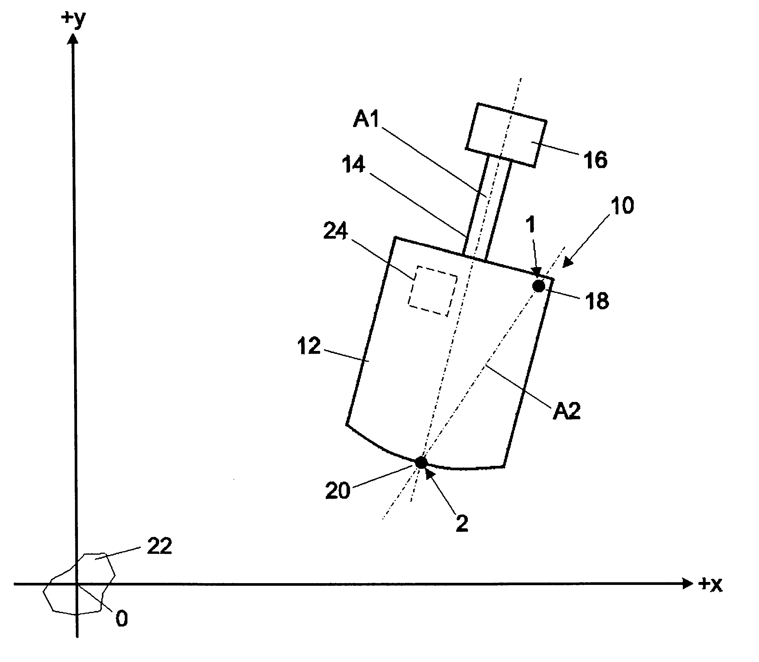
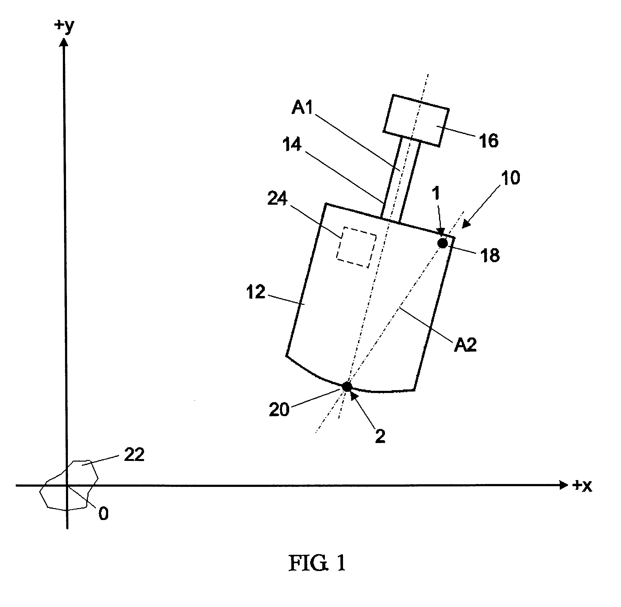
The present invention consists of a novel two-antenna positioning system and a corresponding computational algorithm for ascertaining the position and orientation of a mobile machine on the surface of a work site, such as the pit of a surface mine. The algorithm is based on the periodic collection of position data for two known points on the body of the machine where positioning apparatus is mounted. Accordingly, the invention requires two positioning-system units dedicated to provide current coordinate data for these two points. The preferred embodiment of the invention utilizes GPS units, but is understood that any other technology capable of determining the three-dimensional position of a selected point on the work machine is suitable for practicing the invention.

Referring to the drawings, wherein like parts are designated throughout with like numerals and symbols, FIG. 1 illustrates in plan view a conventional machine 10, such as a shovel-type excavator, used in surface mining o...


PUM


Abstract

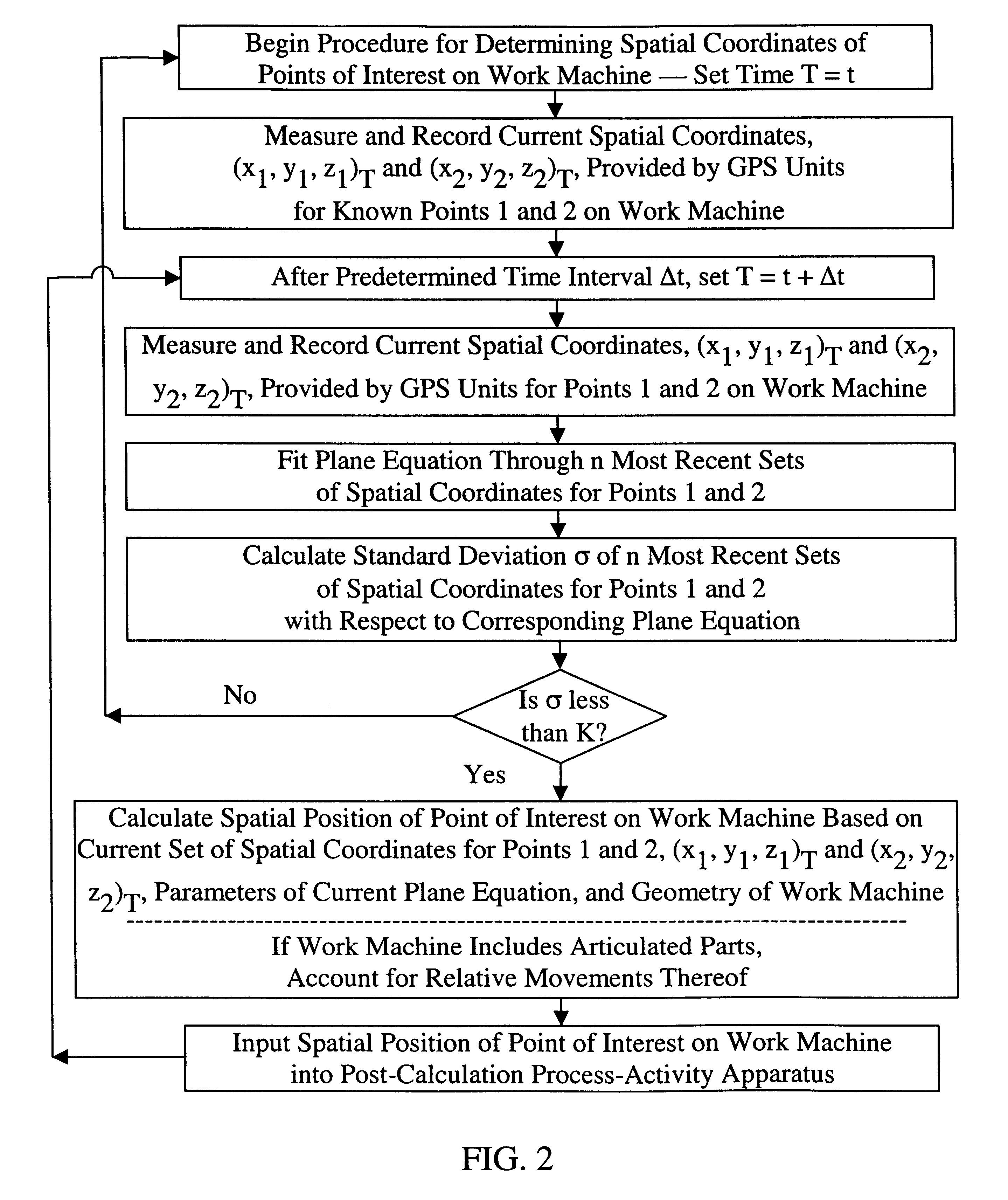
Two GPS units are mounted at two separate points on the body of a work machine to periodically measure their three-dimensional coordinates with respect to a chosen reference system. As soon as two sets of measurements are recorded, a plane is fitted through the four points so collected and it is used to determined the current orientation of the machine. As each additional set of position data is collected at predetermined intervals for the two points on the machine, a new plane equation is calculated to update the orientation of the machine based on a predetermined number of prior measurements. Standard-deviation analysis is used to check the validity of each plane calculation and the process is restarted when the deviation is found to be greater than an acceptable parameter. Based on the current coordinates of the two GPS antennae, the current orientation plane so calculated, and the known geometry of the work machine, the current position of its critical components can be determined as well irrespective of the specific motion pattern of the machine.

Description

1. Field of the InventionThis invention is related in general to the field of equipment automated control and, in particular, to a system for determining the position and orientation of various components of a work machine operating on the grounds of a surface mine.2. Description of the Related ArtSurface mines utilize a variety of work machines for excavating and transporting ore, grading and stabilizing roadways and slopes in the mine pit, and providing all support functions necessary to the operation of a mine. Most work machines, such as excavators, shovels, backhoes and the like, are human-operated, mobile pieces of equipment constantly being moved around on the surface of the mine. Skilled operators ensure that each work machine is positioned in the right place and optimally oriented to perform its intended function. For example, an excavator operator will ensure that the undercarriage of the machine is sufficiently close to the minable seam and that its boom is oriented so as...

Claims


Application Information

Patent Timeline
IPC IPC(8): G01S5/02G01S19/19
CPCG01S5/0247
Inventor DIZCHAVEZ, RUBEN FLORES
Owner MODULAR MINING SYSTEMS
Learn More