Apparatus and method for changing dies

a technology of apparatus and dies, applied in forging presses, forging/pressing/hammering apparatuses, shaping tools, etc., can solve the problems of short life of rolls, large size of the entire system, and many problems with vibration and cos

Inactive Publication Date: 2001-03-13
JFE STEEL CORP +2
View PDF20 Cites 33 Cited by
  • Summary
  • Abstract
  • Description
  • Claims
  • Application Information

AI Technical Summary

Problems solved by technology

2. Conventionally, a rough rolling mill is used to roll a slab. The slab to be rolled may be as short as 5 m to 12 m, and a plurality of rough rolling mills are required to roll the slab or the slab must be rolled backwards and forwards in a reversing rolling system, to obtain the predetermined thickness of the slab. In addition, it is planned to use a reduction press machine of which an example is shown in FIG. 3. The example shows a case in which cranks and connecting rods are used; the cranks 104 are connected to the dies 102 installed above and below the slab 101, through connecting rods 103, and the dies 102 are moved up and down to press on the slab. The slab 101 is moved by pinch rolls 106 and the transfer table 107.
However, such a rough rolling mill with large diameter rolls is difficult to design and manufacture because of its high cost, and furthermore rolls with a large diameter must rotate at a low speed so that the rolls cannot be cooled easily, which results in a short life for the rolls.
As a res

Method used


Image

  • Apparatus and method for changing dies
  • Apparatus and method for changing dies
  • Apparatus and method for changing dies

Examples


third embodiment

(Third embodiment)

FIG. 13 shows the third embodiment of the plate reduction press machine according to the present invention, and the numerals used in the drawing refer to the same objects as those in FIGS. 5 to 9.

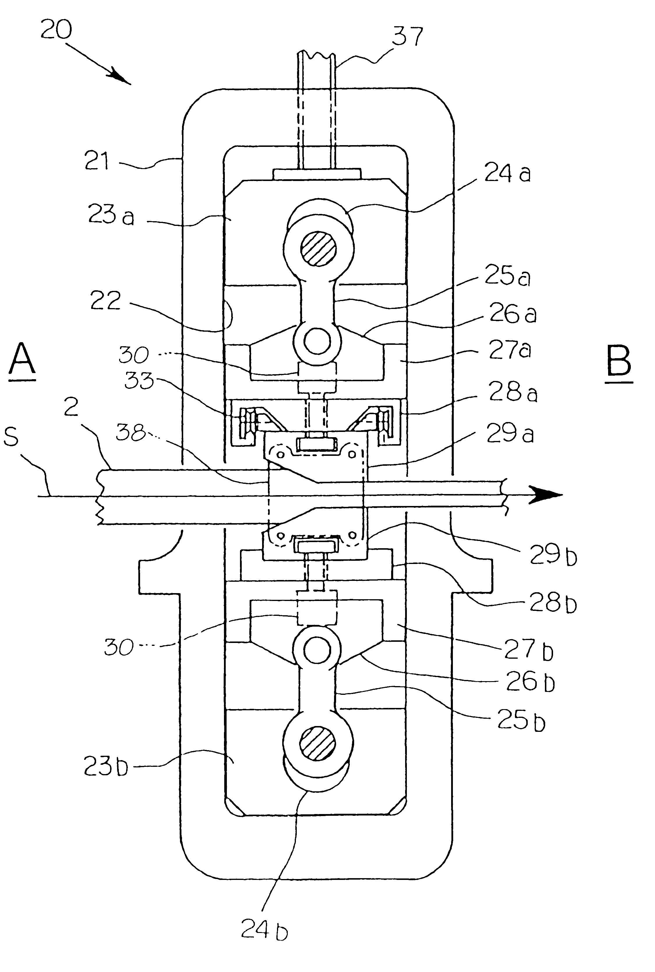
Die changing mechanisms 61 are arranged on both sides of the transfer line S, and each mechanism comprises a rack 63 provided with external guide rails 62 that can be correctly aligned with the support holder guide rails 31 of the press machine 20 and which allow the die rollers 33 to roll and move thereupon, a hydraulic cylinder 64 that can raise and lower the external guide rails 62 relative to the rack 63, a wire rope 65 of which one end is connected and fixed to one of the die fastening members 38 on one side of the transfer line S and the other end is connected and fixed to the other die fastening member 38 on the other side of the transfer line S, and a winch 66 that pulls the wire rope 65 towards one or, the other side of the transfer line S as selected.

The rack 63 ...

fourth embodiment

(Fourth embodiment)

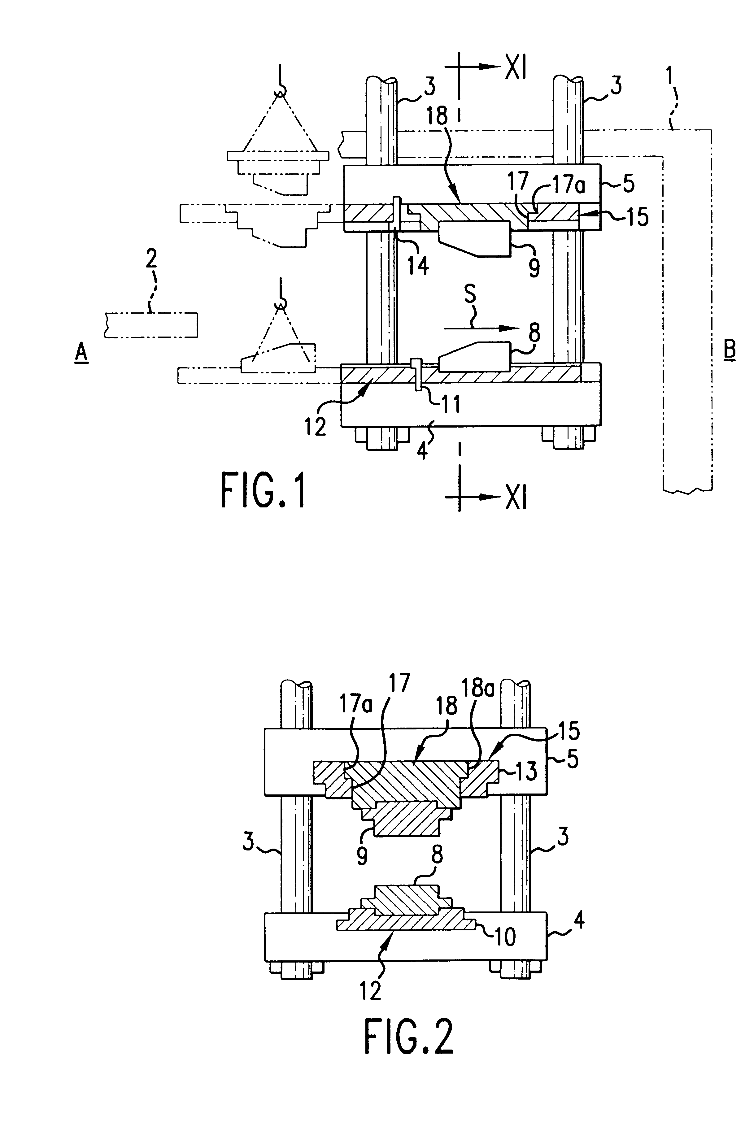
FIG. 14 is a plan view showing the fourth embodiments according to the present invention, and FIGS. 15 and 16 are sectional views along the A--A line in FIG. 14. The status of the dies shown in FIGS. 15 and 16 are during operation and during replacement, respectively.

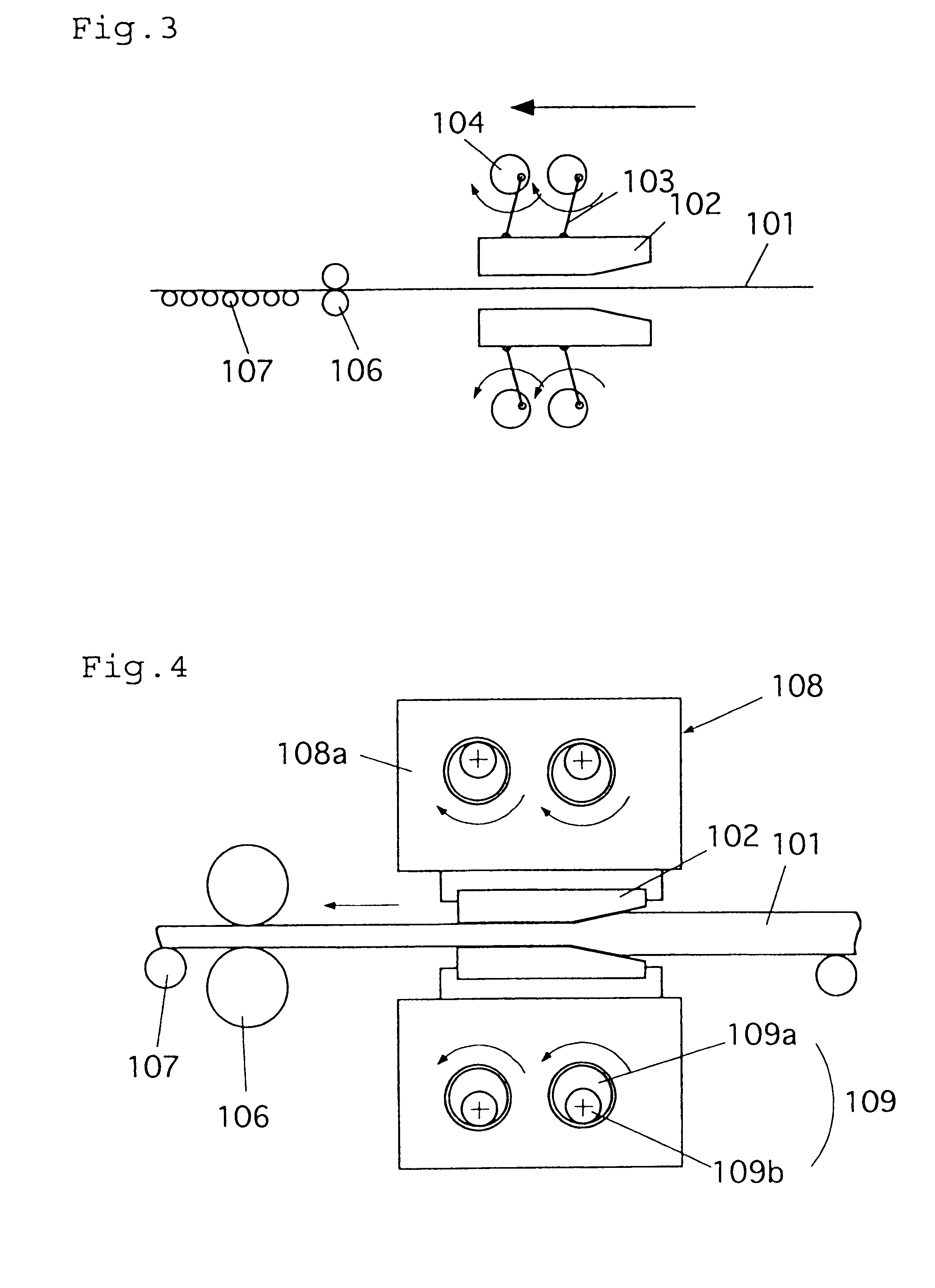
As shown in FIGS. 14 through 16, the die changing apparatus according to the present invention is a die changing apparatus for a plate reduction press that presses the upper and lower dies 102 mounted on the upper and lower sliders 108 and placed vertically opposite each other, towards a slab 101. In FIG. 14, the plate reduction press is represented only by the 4 columns 111.

As shown in FIGS. 15 and 16, the die changing apparatus according to the present invention comprises upper and lower die holders 110 that are fixed to the upper and lower dies 102, respectively, upper and lower die clamps 112 for fixing the die holders 110 in a detachable manner to the sliders 108, and split rails 114 that extend ...

fifth embodiment

(Fifth embodiment)

FIG. 18 is a plan view showing the fifth embodiment of the die changing apparatus according to the present invention. In FIG. 18, the die changing apparatus based on the present invention comprises changing rails 124 that are a continuation of the split rails 114 on the opposite side to the changing rails 116, with supporting surfaces flush with the supporting surfaces of the raised split rails 114 and extending horizontally outside the press machine, and a die changing clamp moving apparatus 126 that slides the upper and lower die holders with another set of dies, located on the changing rails 114, on to the raised split rails. The die changing clamp moving apparatus 126 can comprise a car, cylinder, ram drive, etc. The other component parts are the same as those of the fourth embodiment shown in FIG. 14.

When dies are replaced according to the present invention using the die changing apparatus shown in FIG. 18, after completing the aforementioned steps A through C...


PUM

PropertyMeasurementUnit
Thicknessaaaaaaaaaa

Abstract

The die changing apparatus for a plate reduction press machine, comprises an upper die support holder 28a and a lower die support holder 28b that are arranged vertically on opposite sides of a transfer line, and support holder guide rails 31 installed on the upper die support holder and extending substantially horizontally in the lateral direction of the transfer line, and an upper die 29a and a lower die 29b are mounted on the upper and lower die support holders, respectively using the rollers onto the dies, fixing devices 30 that fix the upper and lower dies on the upper and lower die support holders, respectively, die fastening members 38 which are placed on each side of the upper and lower dies, opposite each other in such a manner that they can be fastened to both dies, and a die changing mechanism that can move one of the die fastening members in a direction perpendicular to the transfer line.

Description

1. Technical Field of the InventionThis invention relates to apparatus and method for changing dies, and a press dies for a plate reduction press machine.2. Prior Art1. FIGS. 1 and 2 show an example of a conventional plate reduction press machine; the machine comprises a frame 1 installed at a predetermined location on a transfer line S, provided with guide columns 3 such that the material to be pressed 2 can be moved inside the frame 1, a lower die holder 4 fixed substantially horizontally at the lower ends of the guide columns 3, an upper die holder 5 connected to the guide columns 3 so that it can be freely raised and lowered in opposition to the lower die holder 4 across the transfer line S, a crank shaft (not illustrated) located above the die holder 5, extending substantially horizontally in a direction orthogonal to the transfer line, and supported on the frame 1 by bearings on the non-eccentric portions, and a lower die 8 and an upper die 9 mounted on the lower die holder 4 ...

Claims


Application Information

Patent Timeline
IPC IPC(8): B21B15/00B21J1/04B21J1/00
CPCB21B15/0042B21J1/04B21B2203/36Y10T483/1729Y10S100/918Y10T483/10B21B13/18
Inventor DODO, YASUSHIIDE, KENICHINARUSHIMA, SHIGEKITAZOE, NOBUHIROFUJII, YASUHIROMASUDA, SADAKAZUYAMASHINA, SHUICHIIKEMUNE, SHOZO
Owner JFE STEEL CORP
Why Eureka
Try Eureka