Image display apparatus
- Summary
- Abstract
- Description
- Claims
- Application Information
AI Technical Summary
Problems solved by technology
Method used
Image
Examples
Embodiment Construction
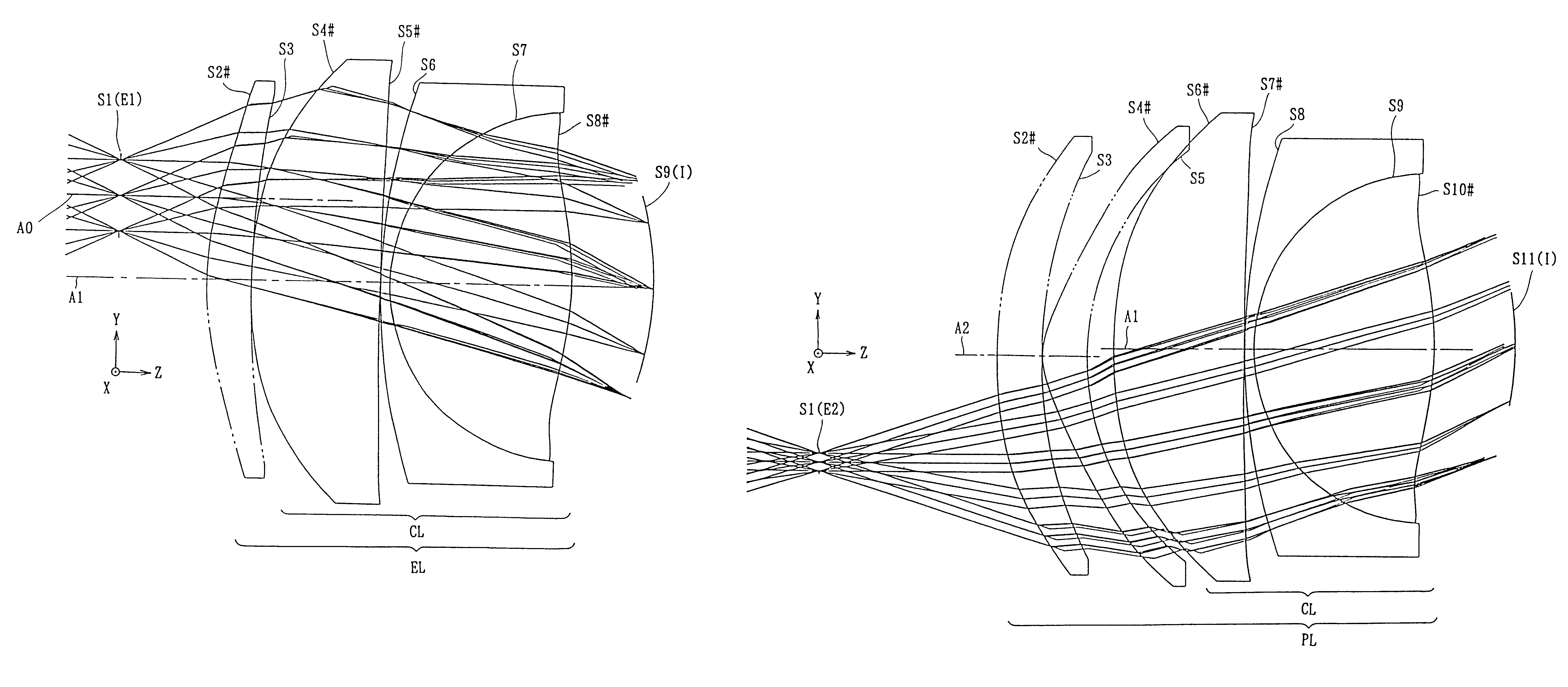
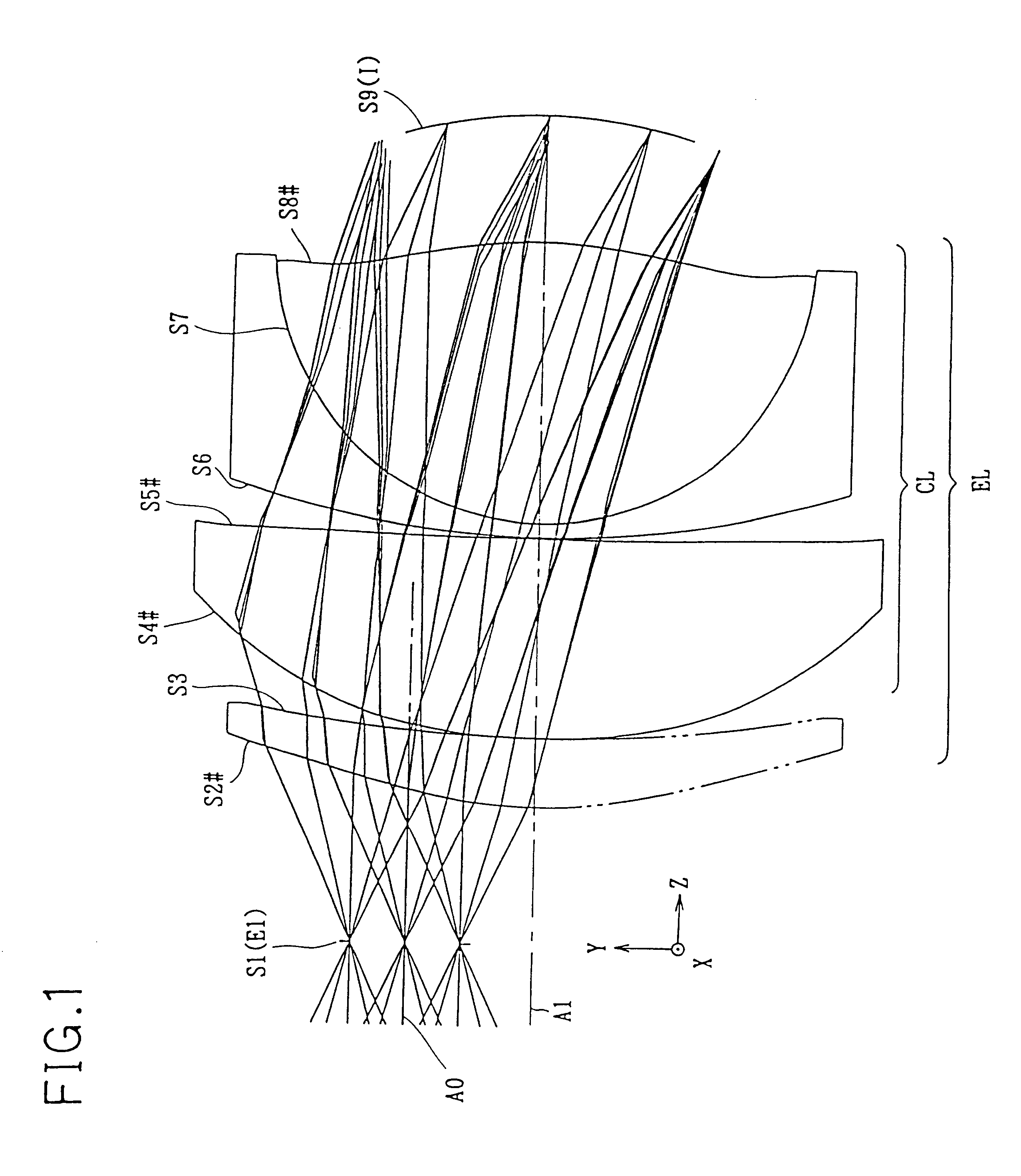
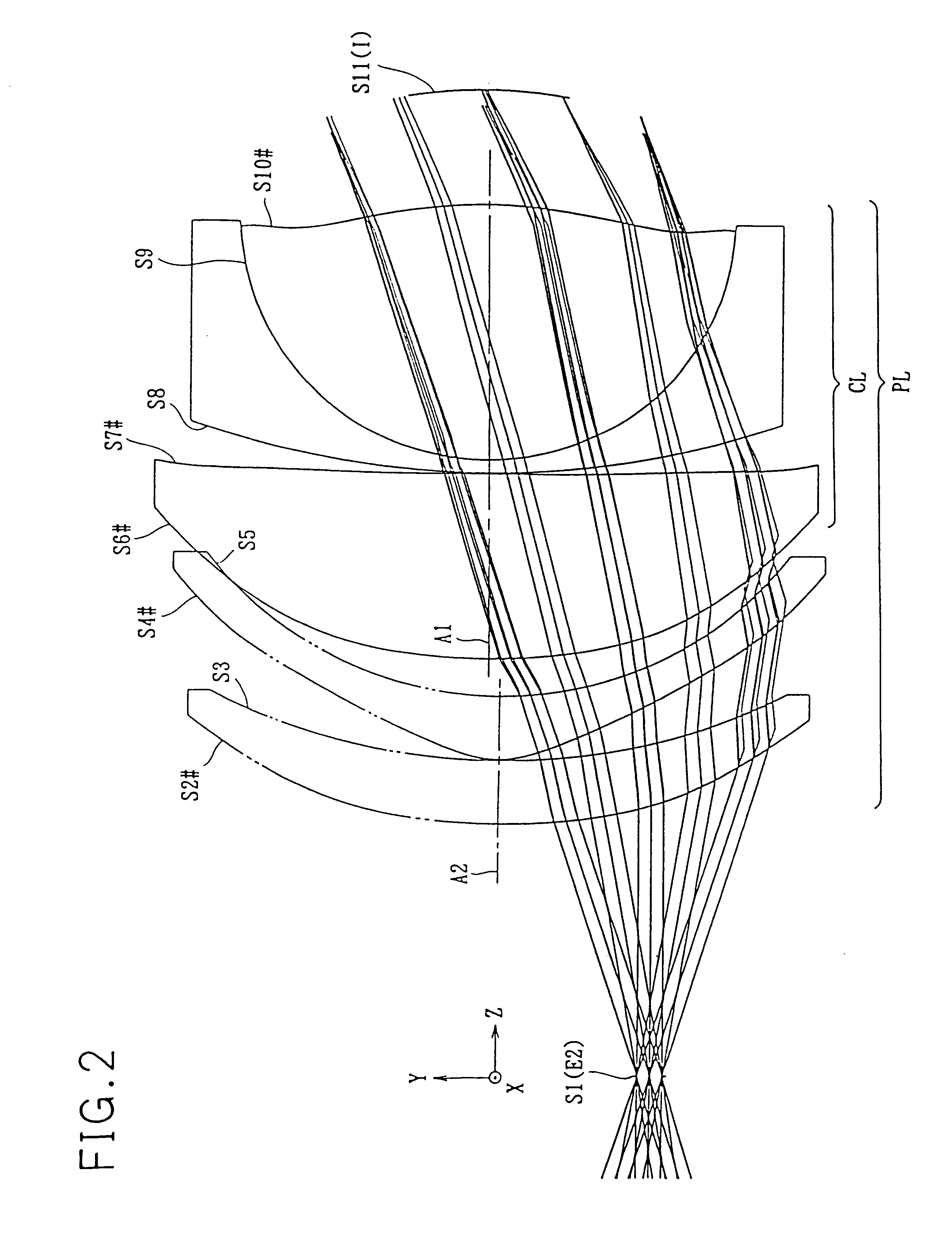
Hereinafter, practical optical arrangements (Examples 1 to 6) of the image display apparatuses embodying the present invention will be presented with reference to the construction data and the spot diagrams of their eyepiece and projecting optical systems (EL and PL). Tables 1, 3, 5, 7, 9, and 11 list the construction data of the eyepiece optical system (EL) employed in Examples 1 to 6, respectively, and Tables 2, 4, 6, 8, 10, and 12 list the construction data of the projecting optical system (PL) employed in Examples 1 to 6, respectively. FIGS. 7, 9, 11, 19, 21, and 23 are spot diagrams of the eyepiece optical system (EL) employed in Examples 1 to 6, respectively, and FIGS. 8, 10, 12, 20, 22, and 24 are spot diagrams of the projecting optical system (PL) employed in Examples 1 to 6, respectively. Examples 1 to 6 respectively correspond to the first to sixth embodiments described above. FIGS. 1, 3, 5, 13, 15, 17, and FIGS. 2, 4, 6, 14, 16, 18 which respectively show the optical arra...
PUM
 Abstract
Description
Claims
Application Information
 - R&D
- Intellectual Property
- Life Sciences
- Materials
- Tech Scout
- Unparalleled Data Quality
- Higher Quality Content
- 60% Fewer Hallucinations
Browse by: Latest US Patents, China's latest patents, Technical Efficacy Thesaurus, Application Domain, Technology Topic, Popular Technical Reports.
© 2025 PatSnap. All rights reserved.Legal|Privacy policy|Modern Slavery Act Transparency Statement|Sitemap|About US| Contact US: help@patsnap.com


