Vacuum system for an I.S. machine

a vacuum system and i.s. machine technology, applied in the field of improved vacuum systems, can solve the problems of time-consuming, time-consuming, and periodic cleaning of vacuum passages

Inactive Publication Date: 2001-03-20
EMHART GLASS SA
View PDF2 Cites 5 Cited by
  • Summary
  • Abstract
  • Description
  • Claims
  • Application Information

AI Technical Summary

Problems solved by technology

A disadvantage to the vacuum process is the tendency of the vacuum to draw in fine glass particles and dirt so that the vacuum passages need to be cleaned periodically.
This requires that the passages be cleaned in place which is time consuming because the mechanism is not very accessible.
Another option is to change out the housing which supports the vacuum manifold but this is time consuming because of its location.

Method used


Image

  • Vacuum system for an I.S. machine
  • Vacuum system for an I.S. machine
  • Vacuum system for an I.S. machine

Examples


Embodiment Construction

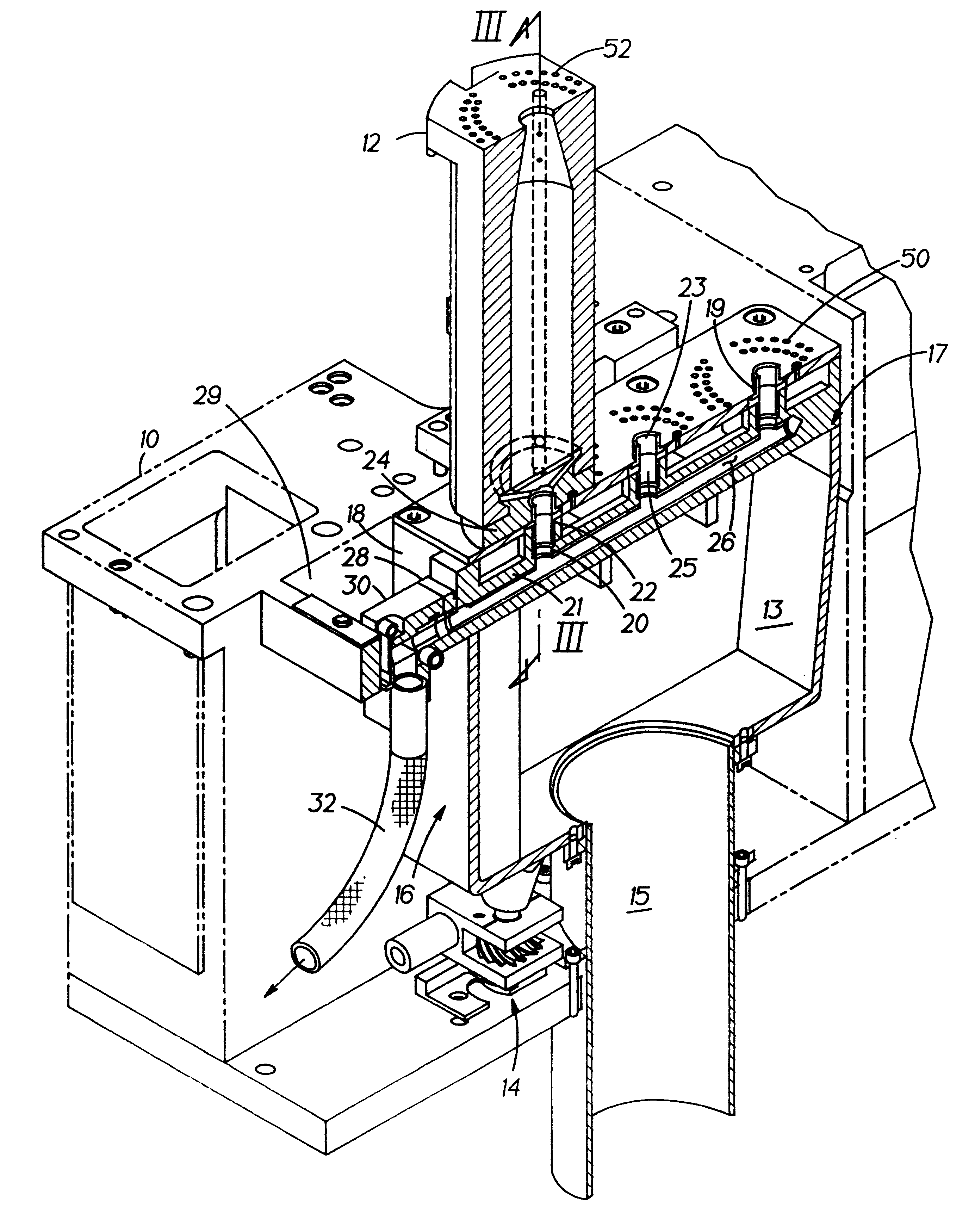
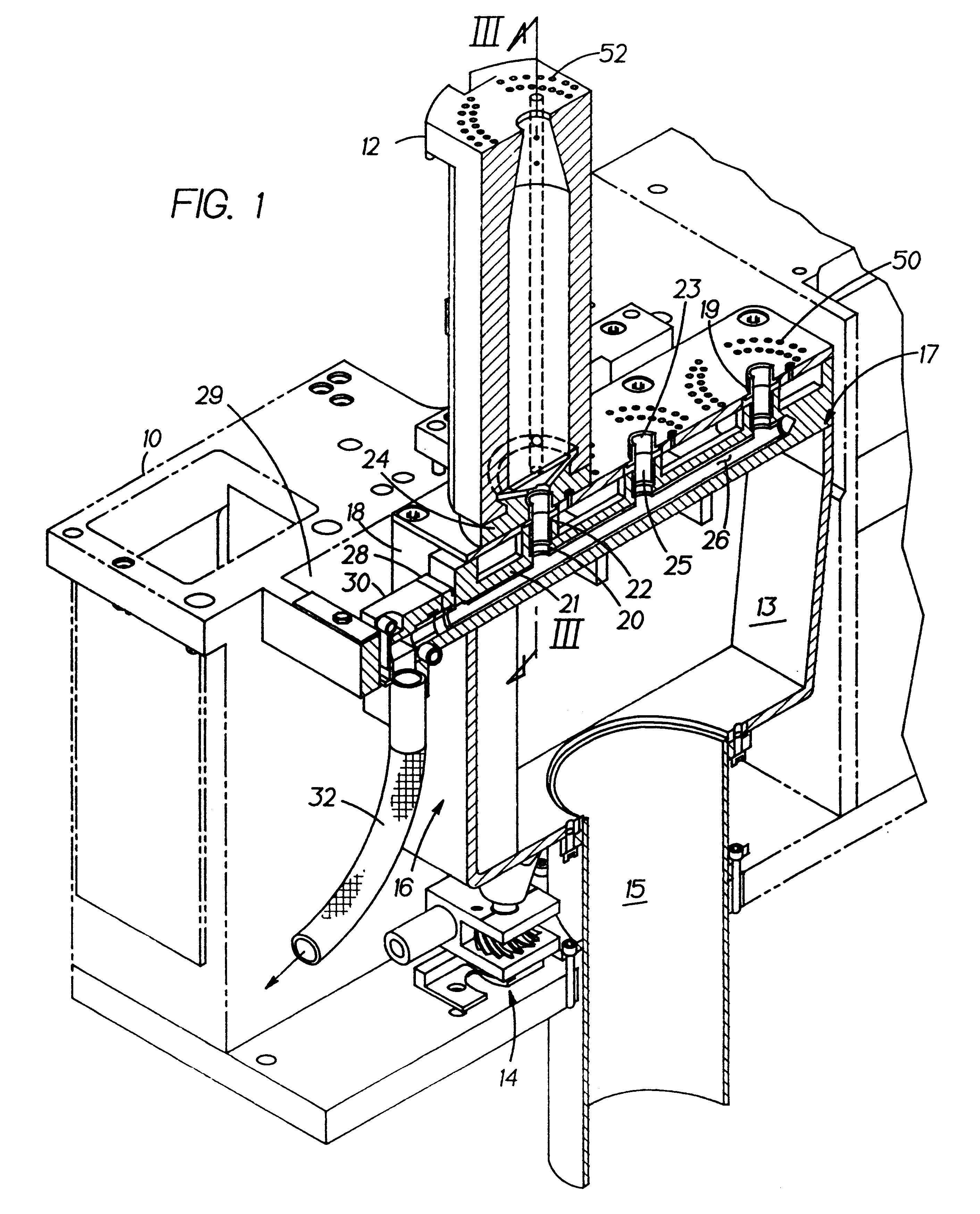
A section frame 10 of an I.S. machine has a mold opening and closing mechanism (not shown for clarity purposes) which supports at least one opposed pair of mold halves 12 which displaces the opposed mold halves from a remote position to an advanced position (FIG. 1) where the are in forced engagement. Mounted to the section frame 10 by a raising and lowering mechanism 14 is the bottom housing 13 of a vacuum mechanism 16. The bottom housing is open 17 at the top and an inlet conduit 15 connects to its bottom. The open top 17 is closed by a two piece top. One piece is an annular manifold housing 18 which is secured to the top of the bottom housing. The manifold housing supports an integral vacuum manifold 21 which has at least one vertical outlet conduit 20 which is open at the top. The second piece of the two piece top is a top plate 29 which has a corresponding number of vacuum holes 19. There is a two piece coupling 22 for each top plate hole and each coupling has an upper tubular ...


PUM

PropertyMeasurementUnit
lengthaaaaaaaaaa
weightaaaaaaaaaa
timeaaaaaaaaaa

Abstract

A vacuum system is disclosed for opposed engaged pairs of blow mold halves on a section of an I.S. machine. The system includes a bottom housing which is open at the top and closed by a top plate assembly including a top plate having a vertical opening for each of the opposed pairs of blow mold halves and an annular manifold support portion below the top plate. A vacuum manifold which has a cylindrical inlet conduit and a vertical outlet conduit beneath each of the top plate vertical openings is supported by the annular mold support portion. A vacuum tube slides into the cylindrical inlet conduit and is mounted on the annular manifold portion. The vacuum tube has a hole for communicating with each of the vacuum manifold vertical outlets.

Description

The present invention relates to I.S. (individual section) machines which transform gobs of molten glass into bottles in a two step process and more particularly to the vacuum mechanism for that machine.The first I.S. machine was patented in U.S. Pat. No. 1,843,159, dated Feb. 2, 1932, and U.S. Pat. No. 1,911,119, dated May 23, 1933. An I.S. (individual section) machine has a plurality of identical sections (a section frame in which and on which are mounted a number of section mechanisms) each of which has a blank station which has one or more blankmolds for receiving a corresponding number of gobs of molten glass. The received gobs are formed into parisons having a threaded opening at the bottom (the finish) and a blow station which receives the parisons and forms them into bottles standing upright with the finish at the top. The most recent design for an I.S. machine is disclosed in U.S. Pat. No. 5,830,254 and a conventional system for supplying vacuum is shown in U.S. Pat. No. 4,...

Claims


Application Information

Patent Timeline
Patent Type & Authority Patents(United States)
IPC IPC(8): C03B9/00C03B9/347C03B9/20C03B9/16C03B9/24C03B9/36
CPCC03B9/165C03B9/20C03B9/24C03B9/347C03B9/3627C03B9/3636C03B9/369
Inventor GOTTLIEB, RUSSELL B.VOISINE, GARY R.
Owner EMHART GLASS SA
Why Eureka
Try Eureka