Thread chasing tool and method

a thread chasing and thread technology, applied in the field of chasing threads, can solve the problems of affecting etc., and achieves the effect of reducing the cost of forged tools, and improving the quality of forged tools

Inactive Publication Date: 2001-03-27
KEYS WESLEY CYRUS MR
View PDF11 Cites 27 Cited by
  • Summary
  • Abstract
  • Description
  • Claims
  • Application Information

AI Technical Summary

Problems solved by technology

A very common problem with this oft used rethreading die, is that of starting the die over damaged threads on the end of a stud or bolt.
In most cases, damage to threads occurs at or near the unattached end of a stud making it difficult to engage a rethreading die with proper alignment to the thread pitch of the stud.
Depending on the amount of damaged or inhibited area this process could be very lengthy and laborious.
Expensive or hard to find bolts create similar problems and are often just discarded.
Hand reworking methods are often unsuccessful because of the critical nature of thread pitch and diameters.
However, this modification process is not simple nor is it effective.
Outer hexagonal wall thicknesses lessen with each increasing size in a conventional rethreading die set making it nearly impossible to accomplish this type of hinge modification.
The overall manufacturing process associated with this die would be extremely costly making it relatively unaffordable.
Also, with adjustments necessary for proper cutting of threads, using this type of a rethreading die in tight spaces becomes tedious.
U.S. Pat. No. 5,288,181 to Pinkston issued Feb. 22, 1994 describes a complicated and cumbersome tool for reconditioning and rethreading a stud made up of moveable jaws activated by a cam device.
An extremely difficult tool to use in tight areas requiring both hands to engage with risk of losing one or more segmented parts of the die with the dislodging of the tension spring.
Proper meshing of the member threads and the die threads would be very difficult in areas of inhibited view.
A complicated, inefficient method not allowing for bidirectional passage over inhibited threads or effective use in areas where clearance is of concern.
This is costly and ineffective.

Method used


Image

  • Thread chasing tool and method
  • Thread chasing tool and method
  • Thread chasing tool and method

Examples


Embodiment Construction

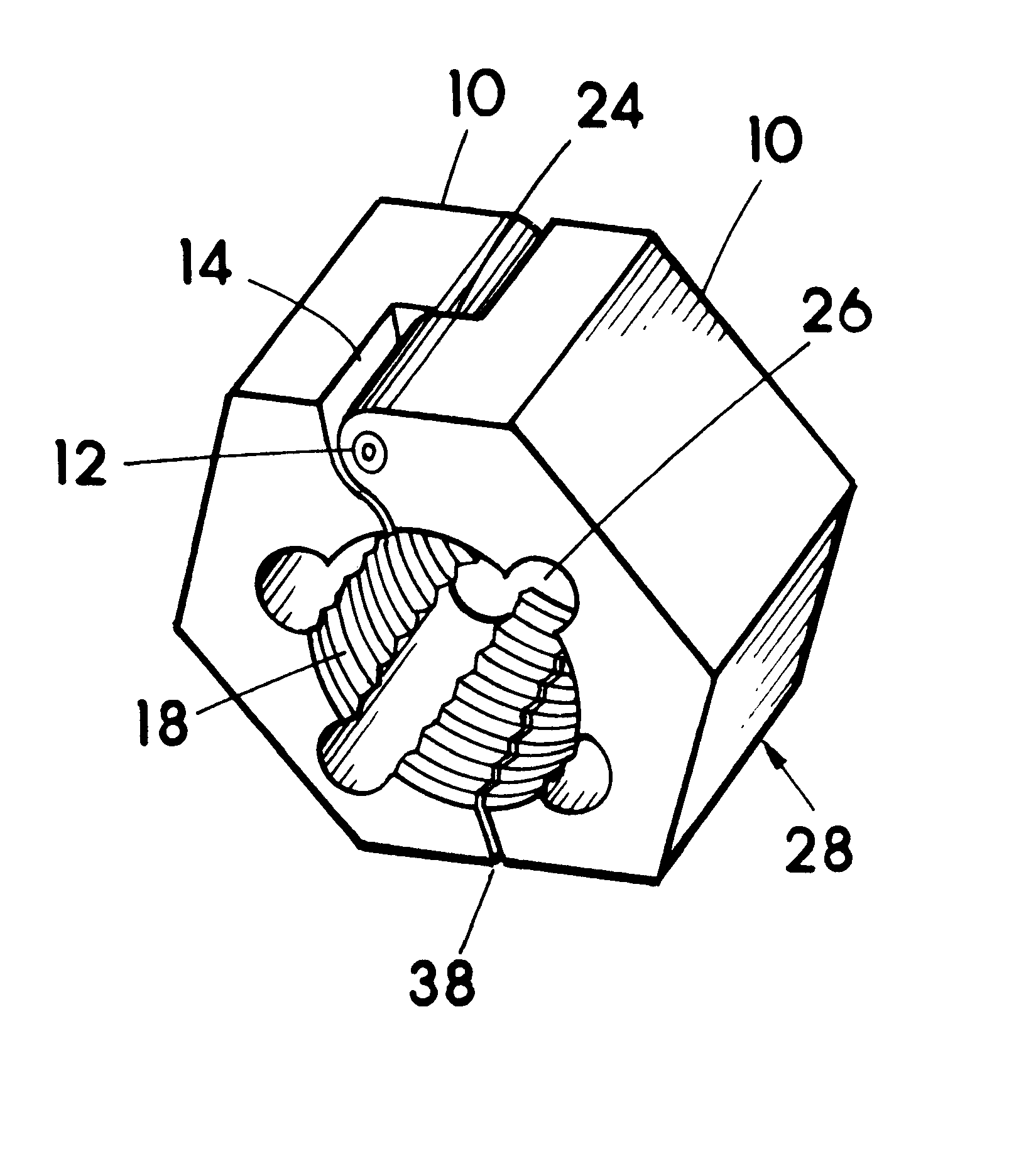
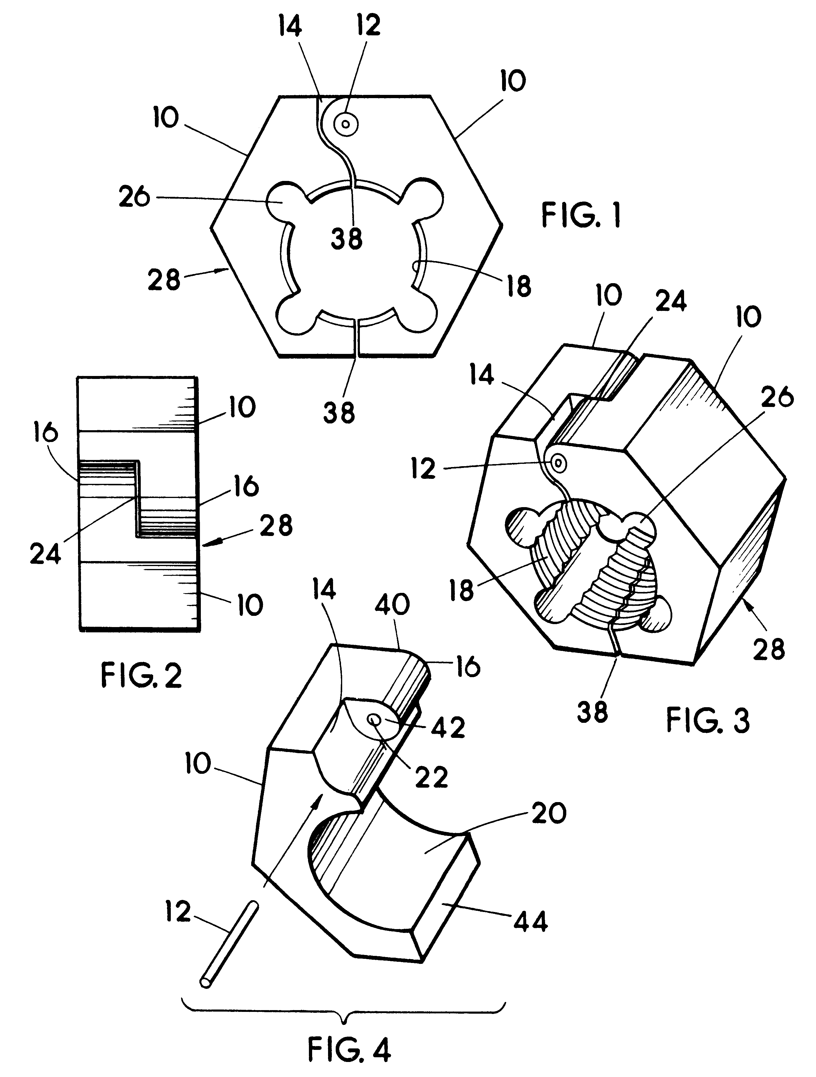
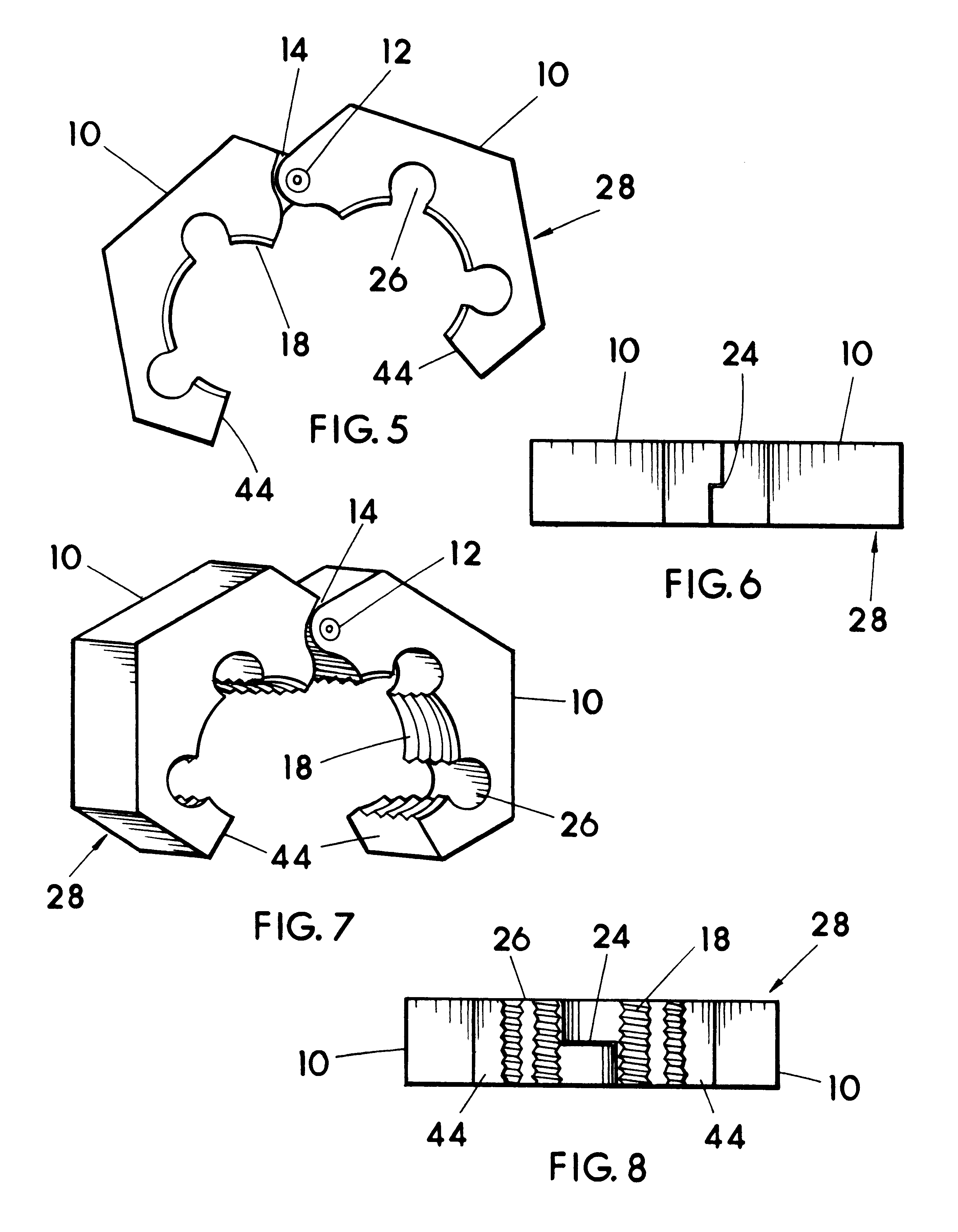
Referring now to FIGS. 1-8, the pivoting split die 28 comprises a pair of opposing and identical main body members or halves 10 each made of a rigid strong metal material. Each main body half 10 being identical to the other allows for a substantially lower cost of manufacturing of die 28 compared to if the halves were not identical, and this due to reduced tooling to be made (one cavity or die stamp or the like needed) and less possible confusion in that there are not any left and right halves to keep track of and mated or matable in the manufacturing of die 28. The body halves 10 when flipped or opposed relative to one another and assembled together define the pivoting split die 28 in general. The "flipped" position may be seen in FIG. 2, and also from examining FIGS. 3-4, 6, wherein the ears 16 are cooperatively mated and the terminal ends 44 are adjacent one another. The pivoting split die 28 may be said to have a front face and an oppositely disposed back face, also identical to...


PUM

PropertyMeasurementUnit
thicknessaaaaaaaaaa
diametersaaaaaaaaaa
thicknessesaaaaaaaaaa

Abstract

A pivoting split thread chasing die for rethreading and cleaning damaged or inhibited studs or bolts; and a method of manufacturing the die. The identical main body halves of the pivoting split die, when assembled together with an assembly pin form a pivoting split die with opposing front and rear faces and a hexagonal outside periphery. Threads are formed on the inside periphery of the pivoting split die allowing for engagement with the threads of a stud or bolt. One or more material reliefs are formed on the inside periphery of the pivoting split die to enhance the cleaning and rethreading ability of the pivoting split die threads. These reliefs also serve as points for which debris can escape while performing a rethreading procedure. To rethread or clean a damaged or inhibited bolt or stud, apply an appropriate lubricant to the area to be rethreaded or cleaned. Open up the pivoting split die and install around existing good threads of the stud or bolt and close pivoting split die until minimal closure gap exists. Select the appropriate wrenching tool and work the pivoting split die back and forth (counter-clockwise and clockwise) over the damaged or inhibited threads until the pivoting split die begins to move about the threads freely.

Description

1. Field of the InventionThe present invention pertains to a pivoting die for the cleaning, rethreading or chasing of threads on studs or bolts that have been damaged, rusted or inhibited with paint or other foreign matter build up.2. Description of the Prior ArtA common method or technique currently in use for retreading or cleaning of studs, bolts is with the use of a hexagonal rethreading die. A common rethreading die has a defined entry leading into a central opening having threaded surfaces facing into the opening for thread forming or cutting. Strategically located around the opening are relief areas to permit cuttings or other foreign matter to fall away from the affected areas of the stud or bolt. A very common problem with this oft used rethreading die, is that of starting the die over damaged threads on the end of a stud or bolt. In most cases, damage to threads occurs at or near the unattached end of a stud making it difficult to engage a rethreading die with proper align...

Claims


Application Information

Patent Timeline
Patent Type & Authority Patents(United States)
IPC IPC(8): B23G9/00B23G5/04B23G5/00
CPCB23G5/04B23G9/009Y10T408/904Y10T408/90473Y10T408/9042
Inventor BURNS, BRIAN D.
Owner KEYS WESLEY CYRUS MR
Why Eureka
Try Eureka