
Heat sink

a technology of heat sink and electronic device, which is applied in the direction of accelerators, cooling/ventilation/heating modifications, semiconductor/solid-state device details, etc., can solve the problems of device package cost, overall cost of electronic device, and cooling means

Inactive Publication Date: 2001-03-27
RPX CORP
View PDF13 Cites 64 Cited by
  • Summary
  • Abstract
  • Description
  • Claims
  • Application Information

AI Technical Summary

Problems solved by technology

In many cases, the cost of the cooling means (e.g., the heat sink) plays a significant role in determining the overall cost of an electronic device.
This configuration poses several problems.
Second, the device package is more costly to manufacture due to the need to provide the detents 20 for interfacing with the feet 22.
A third problem is that because the heat sink 10 is attached to the device package 14, the possible configurations of the device package 14 are limited, and thus the flexibility of the heat sink 10 is also limited.
Accordingly, changes in the device package 14 result in costly changes to the heat sink 10.

Method used


Image

  • Heat sink
  • Heat sink
  • Heat sink

Examples


Embodiment Construction

Illustrative embodiments of the invention are described below. In the interest of clarity, not all features of an actual implementation are described in this specification. It will of course be appreciated that in the development of any such actual embodiment, numerous implementation-specific decisions must be made to achieve the developers' specific goals, such as compliance with system-related and business-related constraints, which will vary from one implementation to another. Moreover, it will be appreciated that such a development effort might be complex and time-consuming, but would nevertheless be a routine undertaking for those of ordinary skill in the art having the benefit of this disclosure.

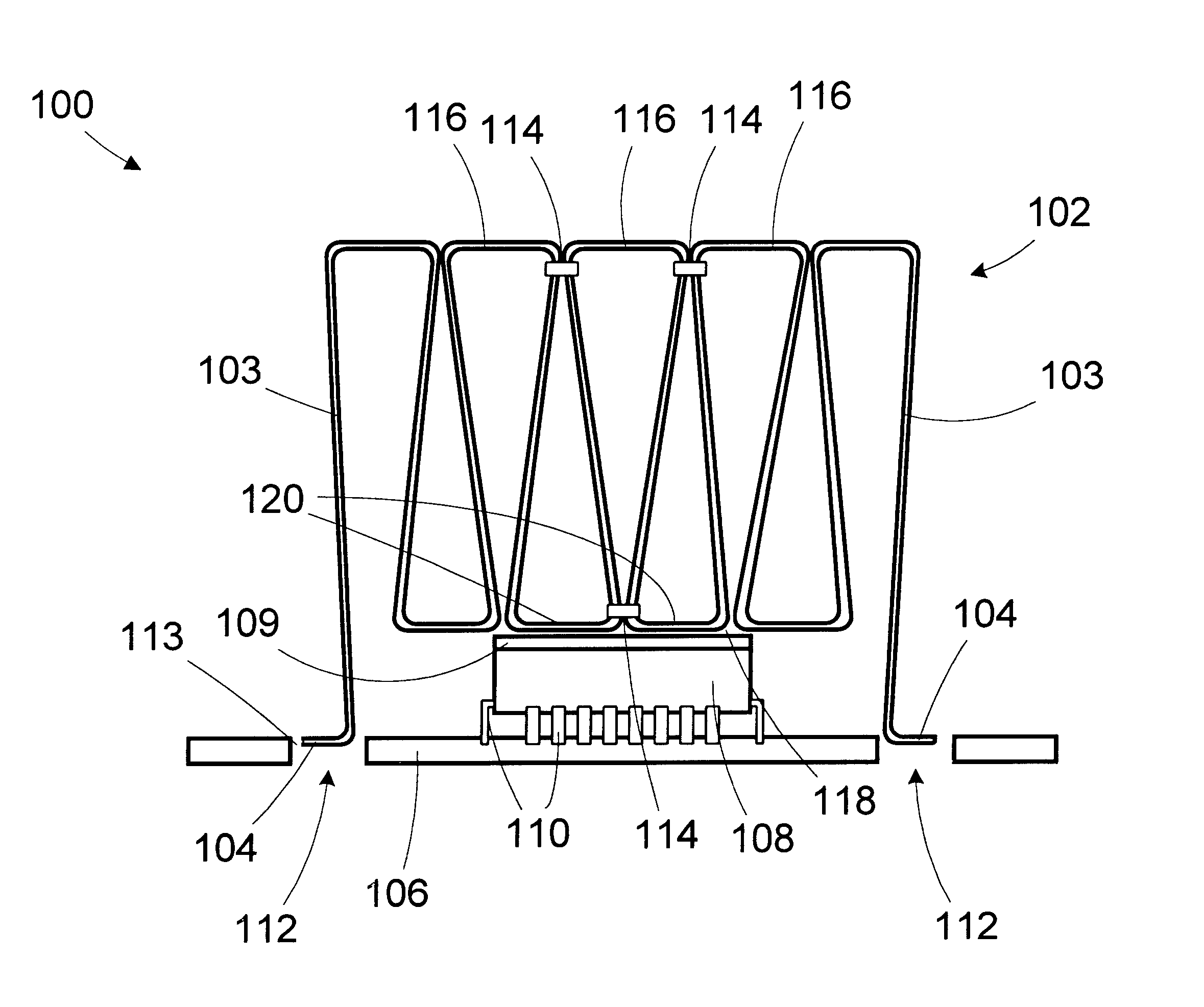
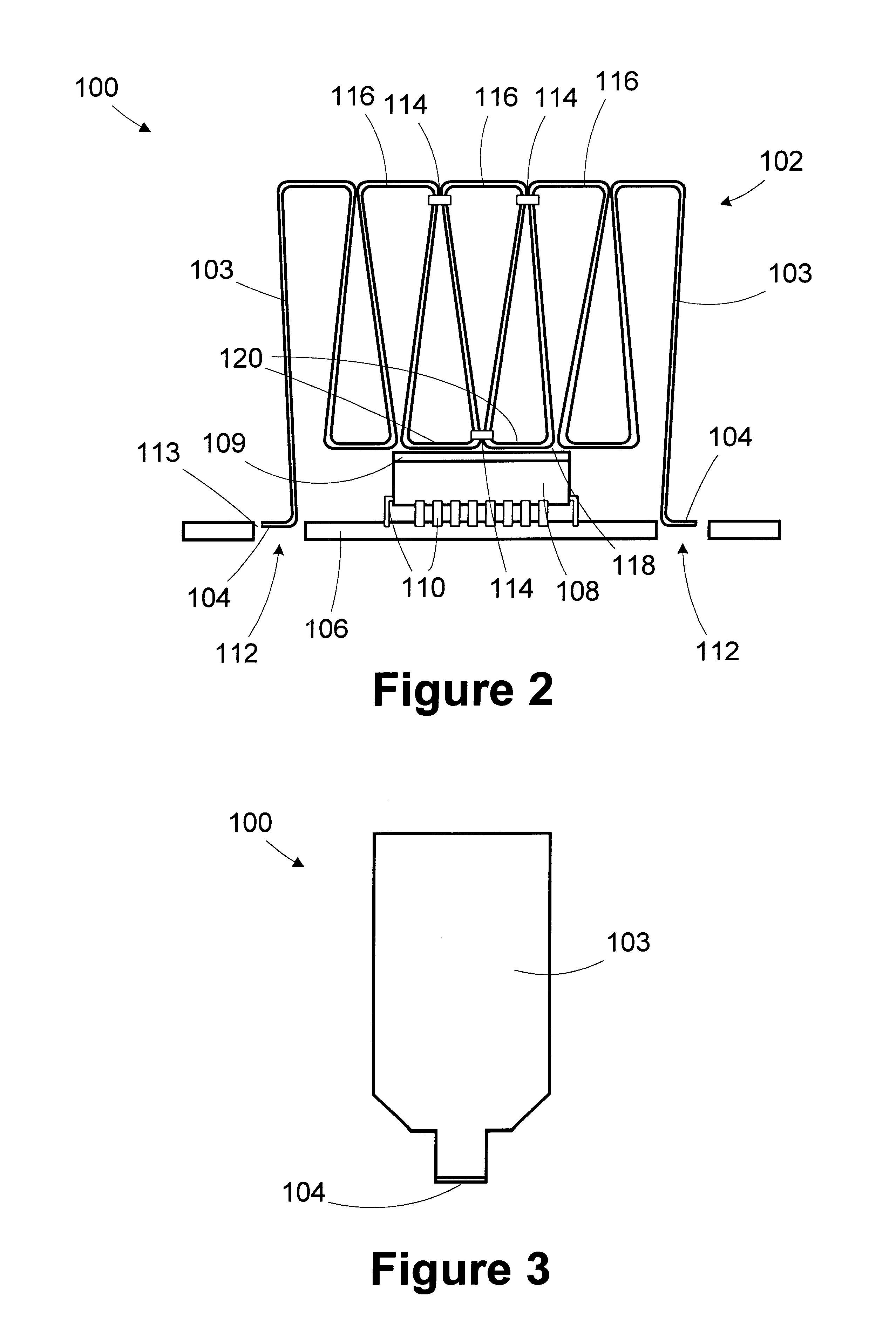
Referring now to FIG. 2, a side view of a heat sink 100 in accordance with the present invention is provided. FIG. 3 shows an end view of the heat sink 100. The heat sink 100 includes a plurality of folds 102. Located on outermost folds 103 are feet 104. The feet 104 interface with a p...


PUM


Abstract

A heat sink includes mounting feet, a plurality of folds, and a clip. Each of the folds has a base portion, and the clip couples at least two of the folds together to inhibit fanning in at least a contact region defined by adjacent base portions. An apparatus includes a printed circuit board, mounting receptacles on the printed circuit board, a heat sink, and a device package. The heat sink includes feet adapted to interface with the mounting receptacles, a plurality of folds, and a base portion defined between the folds. The device package is coupled to the printed circuit board. The base portion of the heat sink contacts at least a portion of the device package.

Description

1. Field of the InventionThis invention relates generally to temperature control for an electronic device, and, more particularly, to a heat sink for cooling an electronic device.2. Description of the Related ArtHeat sinks have been widely used to cool electronic devices. Generally, a heat sink operates in a convective heat transfer mode. The heat dissipation ability of the heat sink is directly proportional to its surface area. A common technique for cooling an electronic device is to provide a metal plate on a surface of the device package and mount a heat sink to the metal plate. The metal plate provides a conductive pathway between a die contained within the device package and the heat sink. The thermal efficiency of the coupling from the die to the heat sink greatly affects the ability of the heat sink to cool the die.In many cases, the cost of the cooling means (e.g., the heat sink) plays a significant role in determining the overall cost of an electronic device. A manufacture...

Claims


Application Information

Patent Timeline
IPC IPC(8): H01L23/367H01L23/34H01L23/40H05K7/20
CPCH01L23/3672H01L23/4093H01L2924/0002H01L2924/00
Inventor PRINCE, STEPHEN T.COLE, TOBY D.BRUNDIDGE, KEVIN C.TUCKER, LARRY W.
Owner RPX CORP
Features
  • Generate Ideas
  • Intellectual Property
  • Life Sciences
  • Materials
  • Tech Scout
  • Unparalleled Data Quality
  • Higher Quality Content
  • 60% Fewer Hallucinations
Learn More